Audio Test Fixture: Difference between revisions
(Audio Test Fixture pictorial) |
(Added Ideas section and information about the front cavity) |
||
| Line 5: | Line 5: | ||
[[Image:PartsKit.jpg|800px]] |
[[Image:PartsKit.jpg|800px]] |
||
The shaped blocks were milled from 18 mm MDF (a leftover piece of shelf material from Home Depot) on a Taig Tools desktop CNC mill ( http://www.taigtools.com/cmill.html ), using a handcrafted GCode program. The MDF is clamped to the mill table with a couple of screws, then you press a button on the computer, come back later, and the set of pieces is made, requiring only light sanding to clean up the edges. The microphone mounting |
The shaped blocks were milled from 18 mm MDF (a leftover piece of shelf material from Home Depot) on a Taig Tools desktop CNC mill ( http://www.taigtools.com/cmill.html ), using a handcrafted GCode program. The MDF is clamped to the mill table with a couple of screws, then you press a button on the computer, come back later, and the set of pieces is made, requiring only light sanding to clean up the edges. The microphone mounting pocket requires a separate (short) milling run after the set of blocks is clamped together. |
||
The hardest items to obtain were the long screws. I needed a 10-32 x 5" machine screw, but size is hard to find at hardware stores, and even online it is only available in large quantity lots like packs of 600. So I bought 10-32 threaded rod at the local hardware store and cut it to length. |
The hardest items to obtain were the long screws. I needed a 10-32 x 5" machine screw, but size is hard to find at hardware stores, and even online it is only available in large quantity lots like packs of 600. So I bought 10-32 threaded rod at the local hardware store and cut it to length. |
||
| Line 21: | Line 21: | ||
The XO speaker fits snugly in a pocket as shown. The speaker diameter is 21 mm; the rear cavity behind it is 17 mm in diameter, extending through the speaker mount section and a further 9 mm into the end cap section. The rear cavity size was a educated guess; lacking T-S parameters for those speakers, an optimum cavity size was not easy to determine - and it probably doesn't matter much for this purpose anyway. |
The XO speaker fits snugly in a pocket as shown. The speaker diameter is 21 mm; the rear cavity behind it is 17 mm in diameter, extending through the speaker mount section and a further 9 mm into the end cap section. The rear cavity size was a educated guess; lacking T-S parameters for those speakers, an optimum cavity size was not easy to determine - and it probably doesn't matter much for this purpose anyway. |
||
The front (center) cavity is 19 mm in diameter and two sections long. Both speakers "fire" into that center cavity where the one microphone can hear them both. |
|||
| ⚫ | |||
| ⚫ | The microphone fits in a side pocket off the center cavity, surrounded by soft foam. The foam decouples the mic from conducted outside sound that might be picked up by the enclosure. In practice, the foam and the microphone are inserted after the blocks have been bolted together. This photo just shows where it goes. |
||
=== Nearly Complete ... === |
=== Nearly Complete ... === |
||
| Line 36: | Line 38: | ||
There is an additional piece of foam - not shown - on top of the microphone element, so the mic is fully surrounded by foam. |
There is an additional piece of foam - not shown - on top of the microphone element, so the mic is fully surrounded by foam. |
||
=== Ideas === |
|||
==== Testing the External Audio Jacks ==== |
|||
As built, the test fixture is set up for testing the XO's internal speaker/microphone circuitry. The same enclosure could be used to test the external jacks, but the wiring would need to change. The speakers would need an external amplifier with a 3.5 mm phone plug. You could, for example, disconnect the speakers from an external PC speaker setup and connect its amplifier to the speakers in the test fixture. |
|||
The microphone connector would need to be a 3.5 mm phone plug. The XO-1.5's external mic jack is stereo, so to test it fully, you would need an additional microphone element. The enclosure could be modified for a stereo microphone setup by milling another side pocket on a different side. Alternatively, if you remove the black rubber boot that surrounds the mic element, it should be possible to cram two elements into the same side pocket. The elements themselves are 6 mm diameter. The element plus boot is 8 mm diameter. The side pocket is 16 mm diameter. The foam is 4 mm thick, but quite compressible, so two elements should fit. |
|||
It probably makes sense to build a "one flavor fits all" fixture with a connector that could accept either an internal harness or an external harness. That would also cater to the need for replaceable harnesses. |
|||
Revision as of 00:30, 31 December 2009
The Audio Test Fixture is a gadget for speeding up the test process for XO-1.5 boards before they have been assembled into cases. It is an acoustic chamber containing two XO speakers and an XO microphone. They can be connected to the XO board so the firmware selftest code can generate test signals on the speakers and listen to them on the microphone. The fixture is made from MDF (medium density fiberboard), an acoustically "dead" material, thus isolating the interior acoustic chamber from the noisy factory environment.
Parts Kit
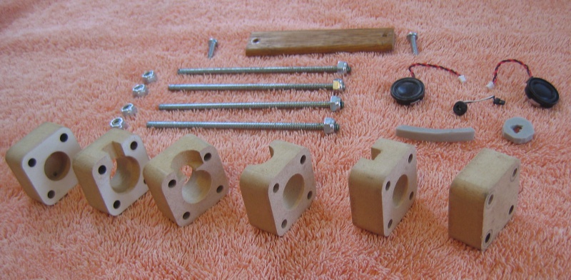
The shaped blocks were milled from 18 mm MDF (a leftover piece of shelf material from Home Depot) on a Taig Tools desktop CNC mill ( http://www.taigtools.com/cmill.html ), using a handcrafted GCode program. The MDF is clamped to the mill table with a couple of screws, then you press a button on the computer, come back later, and the set of pieces is made, requiring only light sanding to clean up the edges. The microphone mounting pocket requires a separate (short) milling run after the set of blocks is clamped together.
The hardest items to obtain were the long screws. I needed a 10-32 x 5" machine screw, but size is hard to find at hardware stores, and even online it is only available in large quantity lots like packs of 600. So I bought 10-32 threaded rod at the local hardware store and cut it to length.
For the next build, I am going to increase the hole size so a 1/4" bolt will fit. 1/4" bolts are easy to find in 4.5" and 5" lengths.
The dark-colored wood strip at the top of the picture is a piece of edge moulding.
The gray foam is 4 mm thickness weather stripping.
Speaker and Microphone Placement
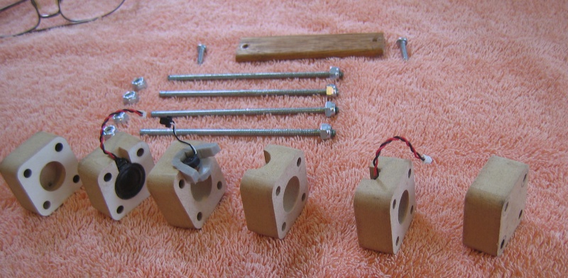
The XO speaker fits snugly in a pocket as shown. The speaker diameter is 21 mm; the rear cavity behind it is 17 mm in diameter, extending through the speaker mount section and a further 9 mm into the end cap section. The rear cavity size was a educated guess; lacking T-S parameters for those speakers, an optimum cavity size was not easy to determine - and it probably doesn't matter much for this purpose anyway.
The front (center) cavity is 19 mm in diameter and two sections long. Both speakers "fire" into that center cavity where the one microphone can hear them both.
The microphone fits in a side pocket off the center cavity, surrounded by soft foam. The foam decouples the mic from conducted outside sound that might be picked up by the enclosure. In practice, the foam and the microphone are inserted after the blocks have been bolted together. This photo just shows where it goes.
Nearly Complete ...
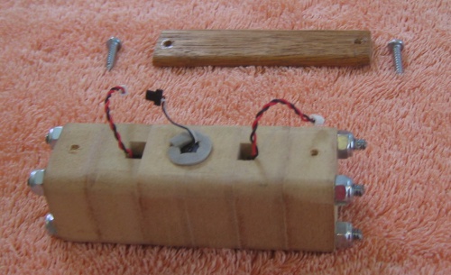
This is what it looks like with all the blocks bolted together.
Fully Assembled, With Strain Relief
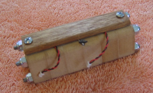
The wooden strip provides strain relief for the wires. In practice, it will be necessary to lengthen those wires so they will reach the connectors on the board. The wiring is likely to be the most fragile part of the unit, so it's probably prudent to make the wiring harness replaceable for use on the manufacturing floor. I expect that Quanta's test engineers will figure something out.
There is an additional piece of foam - not shown - on top of the microphone element, so the mic is fully surrounded by foam.
Ideas
Testing the External Audio Jacks
As built, the test fixture is set up for testing the XO's internal speaker/microphone circuitry. The same enclosure could be used to test the external jacks, but the wiring would need to change. The speakers would need an external amplifier with a 3.5 mm phone plug. You could, for example, disconnect the speakers from an external PC speaker setup and connect its amplifier to the speakers in the test fixture.
The microphone connector would need to be a 3.5 mm phone plug. The XO-1.5's external mic jack is stereo, so to test it fully, you would need an additional microphone element. The enclosure could be modified for a stereo microphone setup by milling another side pocket on a different side. Alternatively, if you remove the black rubber boot that surrounds the mic element, it should be possible to cram two elements into the same side pocket. The elements themselves are 6 mm diameter. The element plus boot is 8 mm diameter. The side pocket is 16 mm diameter. The foam is 4 mm thick, but quite compressible, so two elements should fit.
It probably makes sense to build a "one flavor fits all" fixture with a connector that could accept either an internal harness or an external harness. That would also cater to the need for replaceable harnesses.


