Plug packs
Waveforms
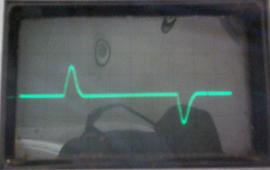
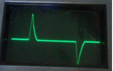
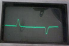
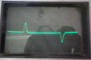
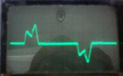
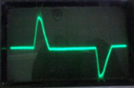
Charger input waveforms, 0.2A/square, screen edges and centre are the input voltage zero crossings
Green wallwart AD5953 ALF, XO1.5 running 93% charge 240V input
as above but run on battery power down to 80% charge then plugged in
Green wallwart Delta ADP17FBA, XO1.5 running 93% charge 240V input
White wallwart Bestek NA0241WAA, XO1.5 running 93% charge 240V input
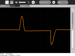
Using the Measure activity and a commercial current transformer to measure charger input current. Drawbacks of Measure are an uncalibrated vertical scale, no synchronisation and no way to establish phase relationship. A home made current transformer can be used [[1]] but it does introduce some distortion into the waveform
Harmonics
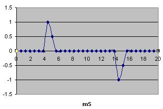
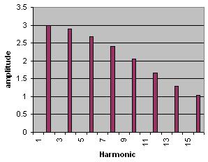
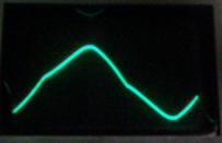
The load is well balanced with respect to leading/lagging power factor, showing only a slight leading or capacitive power factor. The waveform is very rich in harmonics. This could lead to overheating in transformers and generators due to eddy currents.
A harmonic analysis on the following approximation of the waveform
yielded this result
Failures of generators have been reported from OLPC deployments. The following is a likely explanation.
Harmonic currents produce high frequency flux change and cause heating in stator cores. Rotor losses also occur because harmonic currents in the stator will induce currents in the pole faces and amortisseur windings. Higher magnetic core temperatures result in a higher winding temperature. (1)
Power factor has been suggested as a cause and power factor correction discussed, but power factor correction is likely to produce more problems than it fixes.
Caution must be exercised where power factor correction capacitors are used. A resonant condition at one of the harmonic frequencies with some part of the line inductance such as a transformer, on-line motor, or the generator is possible. Excessive and possibly damaging currents at the harmonic frequency can flow through the equipment. Power factor correction capacitors are used primarily for economic reasons; however, they can also be effective in reducing waveform distortion. (1)
Using oversized generators will reduce the temperature rise. There appear to be 'low temperature rise generators' (1) to consider as well but possibly only in larger installations.
Running lightly loaded diesel generators can be problematic, causing glazing of cylinder bores.
The options appear to be
1 load the generator to near maximum capacity and risk failure
2 use petrol generators loaded to considerably less than maximum capacity
3 use diesel generators but include other loads like lighting
Harmonics of other loads
Combining XO charger loads with other loads would allow diesel generators to run reliably at nearer to full load and minimise cylinder glazing.
Resistive loads including incandescent lamps produce no harmonic distortion.
The waveform of compact fluorescent lamps is similar to the XO chargers but the pulse occurs earlier. Having roughly equal wattages of compact fluorescent lamps and XO chargers would double the pulse width and halve the harmonic content.
XO charger and compact fluorescent.
The timing of the current pulses will vary a little from unit to unit, different lamp wattages and brands and different XO states of charge. So, increasing the number of lamps and XO's is likely to smooth the waveform to a smooth double width pulse.
The linear fluorescent with magnetic ballast has low harmonic content and a lagging power factor, that is the waveform is sinusiodal but delayed.
Linear fluorescent lamps will not cause generator overheating provided the VA of the load is within the VA of the generator. If combined with XO charger load, the generator could run nearer to nameplate without overheating.
For comparison with the XO charger, a PC power supply. Vertical scale is 0.4A/square, the waveform has a wider pulse than the XO charger and could be expected to be less stressful on generators and transformers but still a problem.
