Cow Power: Difference between revisions
No edit summary |
|||
| (19 intermediate revisions by 6 users not shown) | |||
| Line 22: | Line 22: | ||
|- |
|- |
||
| valign='center'| |
| valign='center'| |
||
[[Image:Cow2.JPG|thumb|center|300px]] |
[[Image:Cow2.JPG|thumb|center|300px|Picture credits: Carla]] |
||
|} |
|} |
||
| Line 29: | Line 29: | ||
|- |
|- |
||
| valign='center'| |
| valign='center'| |
||
[[Image:CowPower_1.png|thumb|center|300px|Current design]] |
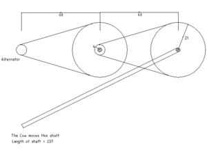
[[Image:CowPower_1.png|thumb|center|300px|Current design (all dimensions in cm The 237cm shaft is not drawn to scale)]] |
||
|} |
|} |
||
| Line 43: | Line 43: | ||
linear velocity of cow = 0.7m/sec |
linear velocity of cow = 0.7m/sec |
||
w(in) = 2.8 rpm (Angular velocity of the shaft rotated by the cow) |
w(in) = 2.8 rpm (Angular velocity of the shaft rotated by the cow) |
||
length of shaft required = 2.37m (The shaft that the cow rotates) |
|||
reduction ratio (big wheel R=21cm, small pulley r=4cm) y=5 X 5 = 25 |
reduction ratio (big wheel R=21cm, small pulley r=4cm) y=5 X 5 = 25 |
||
w(alternator) = w(in) X y = 70rpm |
w(alternator) = w(in) X y = 70rpm |
||
| Line 55: | Line 55: | ||
|- |
|- |
||
| valign='center'| |
| valign='center'| |
||
[[Image:CowPower_2.png|thumb|center|300px|Proposed design]] |
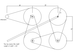
[[Image:CowPower_2.png|thumb|center|300px|Proposed design (all dimensions in cm. The 237cm shaft is not drawn to scale]] |
||
|} |
|} |
||
| Line 75: | Line 75: | ||
Hence the tension in the first belt is about 3500N. This is quite a large value and care must be taken to select the appropriate belt for this purpose. |
Hence the tension in the first belt is about 3500N. This is quite a large value and care must be taken to select the appropriate belt for this purpose. |
||
=Electrical Design= |
=Electrical Design= |
||
| Line 81: | Line 80: | ||
# Regulate current. The XOs at Khairat school have LiFePO4 type batteries. Let us chose a 1A charging current so that with the given capacity of the dynamo, we can charge about 15 XOs simultaneously. See [[Battery Charging]] for more details about all kinds of batteries that are used in the XO |
# Regulate current. The XOs at Khairat school have LiFePO4 type batteries. Let us chose a 1A charging current so that with the given capacity of the dynamo, we can charge about 15 XOs simultaneously. See [[Battery Charging]] for more details about all kinds of batteries that are used in the XO |
||
# Regulate voltage. The XO power supply accepts voltage from 9V - 18V . The charging circuit switches on at 9.85V. Let us chose to fix the voltage that we give the XO at 12V |
# Regulate voltage. The XO power supply accepts voltage from 9V - 18V . The charging circuit switches on at 9.85V. Let us chose to fix the voltage that we give the XO at 12V |
||
Wanted to verify that you had the right numbers above. The [http://wiki.laptop.org/go/Battery_and_power Battery and Power] wiki page mentions that the input voltage range is 11-25 Volts. --[[User:Hbonwit|Hbonwit]] 11:04, 26 April 2008 (EDT) |
|||
<b> More importantly </b> it mentions that "The input current typically exhibits a 1/Voltage characteristics (this e.g. means that an OLPC needs 3 times as much current at 5 Volts than at 15 Volt)." In this case, you might want to design towards the upper end of the voltage spectrum. --[[User:Hbonwit|Hbonwit]] 11:04, 26 April 2008 (EDT) |
|||
==Design approach== |
==Design approach== |
||
| Line 96: | Line 99: | ||
# Hence R1 and R2 can be chosen to be 0.25W type |
# Hence R1 and R2 can be chosen to be 0.25W type |
||
=Alternator vs Dynamo= |
|||
In our earlier design we had used a dynamo taken from Fiat cars (which are common Mumbai as all taxis in Mumbai are Fiats). We had hoped to avoid making extra expenditure of an external 12V battery since dynamos don't require any external source to provide starting current. However in our current design we have changed over to using an alternator. This is because - |
|||
# The dynamo only generates at the rated rpm and not below that. The alternator generates about 1.5A of current even at as low as 70rpm. |
|||
# While the dynamo would have helped avoid an external battery, there would have been a great cost of copper wires to take the current from the dynamo to where the XOs are kept to directly charge them. Using an alternator we'd be charging a car battery kept near the alternator which can be later carried to near the XOs to charge them. So there is no cost advantage obtained while using a dynamo. |
|||
# The dynamo is commonly available in Mumbai but the alternator is easily available all across India |
|||
# All car alternators today have built in rectification and cut-off (output switches off when battery is fully charged) |
|||
=How you can help= |
=How you can help= |
||
| Line 102: | Line 111: | ||
We need inputs in the following areas |
We need inputs in the following areas |
||
# Voltage vs rpm characteristics for some commonly used alternators used in trucks in India. Especially the one used in Tempo 407 |
# Voltage vs rpm characteristics for some commonly used alternators used in trucks in India. Especially the one used in Tempo 407 |
||
# 3500N belt - what kind of a belt would be best for this |
|||
# |
## The one we have in mind is the one used in '''Chakki''' machines used in India (Flour grinding machines used in India). This is a flat belt and is about 2" thick. Also, would a flat belt be better suited for this purpose or a V belt ? |
||
## What about 2-5 parallel belts on the same shaft? The only problem I can foresee is equalizing tension between each belt... |
|||
# Calculations for starting current for an alternator at different rpms |
# Calculations for starting current for an alternator at different rpms |
||
| ⚫ | |||
| ⚫ | |||
=Credits/Acknowledgments= |
=Credits/Acknowledgments= |
||
* Idea and implementation - Arjun |
* Idea and implementation - [[User:Arjs|Arjun]], [[User:Carla|Carla]], [[User:Amitg|Amit]], and now recently Prashant and Sandip |
||
* Thanks to Richard Smith for help in the electrical design. |
* Thanks to Richard Smith for help in the electrical design. |
||
* Thanks to Pranay, Raghav and Sairam for their inputs on the mechanical design. |
* Thanks to Pranay, Raghav and Sairam for their inputs on the mechanical design. |
||
* Thanks to Mr Prabhat (Khalambuli, Mumbai) for his advice on the alternator selection |
* Thanks to Mr Prabhat (Khalambuli, Mumbai) for his advice on the alternator selection |
||
* Thanks to Mr Vipin of Fenner India for his advice |
* Thanks to Mr Vipin of Fenner India for his advice |
||
=Articles/Blogs/Reports related to Cow Power= |
=Articles/Blogs/Reports related to Cow Power= |
||
| Line 129: | Line 138: | ||
| colspan=6 style="background:lightgray; " | |
| colspan=6 style="background:lightgray; " | |
||
|- |
|- |
||
||[[Image:Cow2.JPG|thumb|200px]] |
||[[Image:Cow2.JPG|thumb|200px|Picture by Carla]] |
||
||[[Image:Cow3.JPG|thumb|200px]] |
||[[Image:Cow3.JPG|thumb|200px|Picture by Carla]] |
||
||[[Image:Cow4.jpg|thumb|200px]] |
||[[Image:Cow4.jpg|thumb|200px]] |
||
|- |
|- |
||
| Line 141: | Line 150: | ||
|| |
|| |
||
|- |
|- |
||
| colspan=6 style="background:white; " | |
|||
} |
|||
| ⚫ | |||
==Tonga (Cart) Wheel== |
|||
| ⚫ | |||
==The local Sugarcane juice machine== |
|||
{|border=1 cellpadding=2 cellspacing=0 style="border: 1px #666666 solid; background: #f9f9f9; border-collapse: collapse;" |
|||
| colspan=8 style="background:lightgray; " | |
|||
|- |
|||
||[[Image:sc1.jpg|thumb|200px]] |
|||
||[[Image:sc2.jpg|thumb|200px]] |
|||
||[[Image:sc3.jpg|thumb|200px]] |
|||
|- |
|||
[[Category:Hardware ideas]] |
|||
[[Category:Battery & Power]] |
|||
Latest revision as of 15:04, 26 April 2008
Motivation
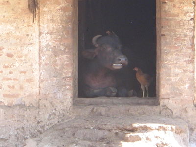
We wanted to develop alternative power solutions at the OLPC pilot project site at Khairat Village. Our approach was to not look from a motor/dynamo etc. point of view. Our approach was to develop power solutions around locally available mechanisms. At the village (pilot site near Mumbai) we explored the ideas of using solar power (in Mumbai sunlight is not consistently strong) , running water (we couldn't find any local water bodies nearby), wind power (no wind in the that area), mounting small dynamos on bicycles (we found out that in that area bicycles aren't that common at all, esp in that village) .But the village had an abundance of cattle - that were being used in the fields. So we decided to design something around that.
Having said that, the solution is of course not a one-for-all solution, but is an example of how locally available mechanisms can be leveraged to charge the laptops. The mechanical and electrical design would be re-usable in a way that other driving mechanisms at other places could be used to drive a dynamo/alternator by following a similar design approach.
We considered using a small motorcycle/moped engine , but that would lead to recurring costs of petrol/diesel for the villagers, hence we decided against it. Minimizing costs, is an important factor for easy replicability.
Current Mechanical Design
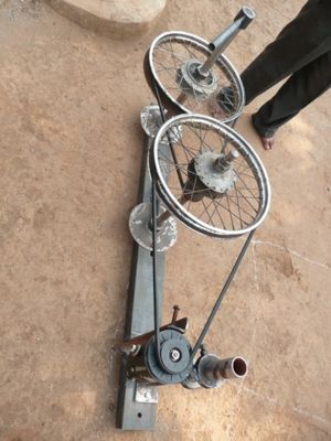
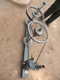
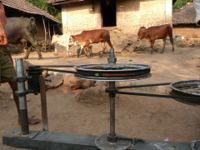
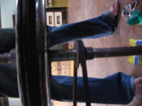
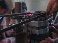
We are using a system of belts and pulleys to get a high rpm at the alternator. This alternator has been taken from the ones used in trucks. The specific model of truck from which this alternator comes from is Tempo 407.
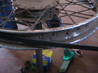
The pulleys and belts are taken from local junkyard shops and are commonly used in cars.
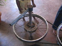
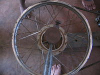
The large rim were also taken from local junkyard shops and are the rims of motorbikes.
Calculations for this prototype are as follows -
linear velocity of cow = 0.7m/sec
w(in) = 2.8 rpm                                (Angular velocity of the shaft rotated by the cow)
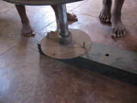
length of shaft required = 2.37m               (The shaft that the cow rotates)
reduction ratio (big wheel R=21cm, small pulley r=4cm) y=5 X 5 = 25
w(alternator) = w(in) X y = 70rpm
70rpm give us about 1.5A current output which is enough to charge 2 XOs.
Proposed Mechanical Design
To get a higher current output from the alternator and hence a higher rpm at the alternator, we need to increase the ratio by which our rpm gets converted. This is a proposed design.
The calculations for the proposed design would hence change to -
reduction ratio = 25 X 25 = 625
w(alternator) = 1700 rpm
This rpm would give us about 10A which is enough to charge 10 XOs simultaneously.
An important factor to consider here would the force/tension in the belt at the slowest rpm. Say our alternator is giving out 12V and 10A output. This amounts to 120W of output power. Assuming losses in the system and a reasonable efficiency of the alternator, lets say that the power input of the system is 200W. That is, the cow is delivering 200W of input power into the system.
P = 200W
w = 2.8rpm
r = .21m
using P = Tw and T = Fr we calculate F as
F = approx 3500N
Hence the tension in the first belt is about 3500N. This is quite a large value and care must be taken to select the appropriate belt for this purpose.
Electrical Design
Requirements
- Regulate current. The XOs at Khairat school have LiFePO4 type batteries. Let us chose a 1A charging current so that with the given capacity of the dynamo, we can charge about 15 XOs simultaneously. See Battery Charging for more details about all kinds of batteries that are used in the XO
- Regulate voltage. The XO power supply accepts voltage from 9V - 18V . The charging circuit switches on at 9.85V. Let us chose to fix the voltage that we give the XO at 12V
Wanted to verify that you had the right numbers above. The Battery and Power wiki page mentions that the input voltage range is 11-25 Volts. --Hbonwit 11:04, 26 April 2008 (EDT)
More importantly it mentions that "The input current typically exhibits a 1/Voltage characteristics (this e.g. means that an OLPC needs 3 times as much current at 5 Volts than at 15 Volt)." In this case, you might want to design towards the upper end of the voltage spectrum. --Hbonwit 11:04, 26 April 2008 (EDT)
Design approach
- Using L200 as the central component - it is cheap, easily available and most of all robust
- Referring to this sample circuit and deriving parameters from this design guide
- To avoid effects of shorting or reversing of supply from dynamo to the L200 circuit a simple full wave bridge rectifier using 1N5408 diodes has been used. Also, a 100uF 35V decoupling capacitor is being used after the rectifier.
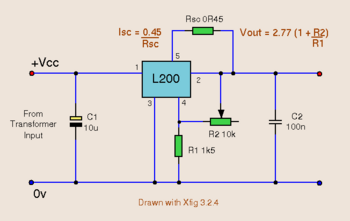
Deriving circuit parameters
- For values of R2 and R1, I referred to table in right column of Page 4 of design guide. Selecting Vo=12V +-4% I get R1= 1K ohm +-1% and R2=3.3K +-1%
- Since Isc = 0.45/Rsc (according to sample circuit design), I chose Rsc=0.47 ohm 1/2 watt
- Current in R2, Ir2=(Vo-Vref)/R2 where Vref = 2.77V. Hence power dissipation in R2, Pr2 = 25.8 mW
- Current in R1, Ir1=Vref/R1 = 2.77mA . Hence power dissipation in R1, Pr1 = 7.7 mW
- Hence R1 and R2 can be chosen to be 0.25W type
Alternator vs Dynamo
In our earlier design we had used a dynamo taken from Fiat cars (which are common Mumbai as all taxis in Mumbai are Fiats). We had hoped to avoid making extra expenditure of an external 12V battery since dynamos don't require any external source to provide starting current. However in our current design we have changed over to using an alternator. This is because -
- The dynamo only generates at the rated rpm and not below that. The alternator generates about 1.5A of current even at as low as 70rpm.
- While the dynamo would have helped avoid an external battery, there would have been a great cost of copper wires to take the current from the dynamo to where the XOs are kept to directly charge them. Using an alternator we'd be charging a car battery kept near the alternator which can be later carried to near the XOs to charge them. So there is no cost advantage obtained while using a dynamo.
- The dynamo is commonly available in Mumbai but the alternator is easily available all across India
- All car alternators today have built in rectification and cut-off (output switches off when battery is fully charged)
How you can help
Your help and inputs would be greatly appreciated. Please use the discussion tab on the top of this page for all your comments. We need inputs in the following areas
- Voltage vs rpm characteristics for some commonly used alternators used in trucks in India. Especially the one used in Tempo 407
- 3500N belt - what kind of a belt would be best for this
- The one we have in mind is the one used in Chakki machines used in India (Flour grinding machines used in India). This is a flat belt and is about 2" thick. Also, would a flat belt be better suited for this purpose or a V belt ?
- What about 2-5 parallel belts on the same shaft? The only problem I can foresee is equalizing tension between each belt...
- Calculations for starting current for an alternator at different rpms
Credits/Acknowledgments
- Idea and implementation - Arjun, Carla, Amit, and now recently Prashant and Sandip
- Thanks to Richard Smith for help in the electrical design.
- Thanks to Pranay, Raghav and Sairam for their inputs on the mechanical design.
- Thanks to Mr Prabhat (Khalambuli, Mumbai) for his advice on the alternator selection
- Thanks to Mr Vipin of Fenner India for his advice
- Article in IT magazine in Netherlands(Courtesy Pascal Scheffers) - http://wiki.laptop.org/go/Image:Netherlands_Cow.JPG
- Article in Hindustan Times, India - http://wiki.laptop.org/go/Image:HT_Cow.pdf
- Computerworld
- Slashdot
Video on Youtube
<youtube>SwcSEcfR464</youtube>
Pictures of current prototype
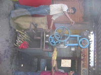
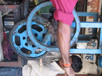
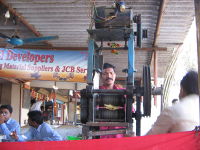
Other solutions to exploreTonga (Cart) WheelUse a Tonga wheel to increase the rpm ratio further. The Tonga wheel is a large wheel - much larger than the ones used in cars/motorcycles. See here to know what a Tonga is. The local Sugarcane juice machine |
||||||||||||||||
