XO 1.5 A1: Difference between revisions
No edit summary |
|||
| Line 73: | Line 73: | ||
The microphone inputs need an ECO to work. If yours doesn't work, let wad know. |
The microphone inputs need an ECO to work. If yours doesn't work, let wad know. |
||
===Camera=== |
|||
If you intend on using the camera, there are two issues: |
|||
# No existing version of OFW checks the value of the ''serial enable'' jumper ([http://dev.laptop.org/ticket/9377 Trac #9377]) |
|||
# You will need to jumper pin 2 to pin 4 of U1 together (U1 is an small five pin device, |
|||
not populated). |
|||
===Power-On Issues=== |
===Power-On Issues=== |
||
Revision as of 03:01, 25 June 2009
XO-1.5 Laptop Alpha test model first A-Test, also known as A1.
Description
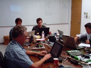
The A1 bring up happened in late May, 2009. Power up of the first OLPC XO-1.5 electronics prototype boards occurred May 21, 2009. Power distribution debugging continued over the weekend, and formal debug and BIOS bring up started Monday, May 25, 2006 at Quanta Computer's labs in Gueishan near Taipei, Taiwan. Due to errors in the layout, only ten of these boards were obtained by OLPC for testing.
The current distribution of these boards is limited.
Supporting documentation for these boards (all in PDF):
Please note that production boards will likely have different pin mappings and connector locations.
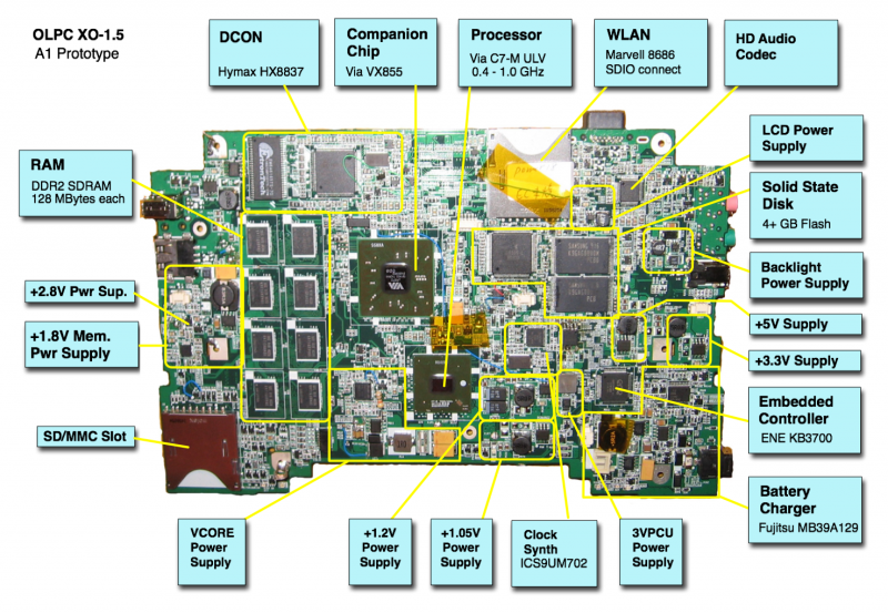
Identification
- Bare circuit board, no case or display
- Blue wires near RTC battery connector
- SD slot for WLAN
Photographs:
Software Support
XO-1.5 use Q3Exx firmware releases. These are currently only available through secure ftp to dev.laptop.org/home/wmb/
Check the XO 1.5 EC dev changelog for information about the latest EC firmware (integrated into the above OFW releases).
A Linux image for the A1 is available at http://dev.laptop.org/~cjb/f11-1.5/os8/os8.img.gz.
To install on an XO-1.5, you can run:
zcat os8.img.gz > /dev/hda
Restrictions
Heat
If you have a laptop in a case, please don't operate it for long periods of time with the back cover of the laptop in place. While a cover is provided for shipping, it is not screwed down and may be removed by simply removing the two green bumpers at the bottom sides of the display unit. Each is held in place by a single screw.
If you have a heat spreader (doubtful), this rule may be violated. A heat spreader (a thin aluminum plate) distributes the heat to avoid overheating the major sources of heat.
WLAN
What WLAN ? There is an SD slot, if you want to plug in an adapter of your choice.
USB
In order to fit an A1 boards into a case, one of the USB sockets is missing (it was layed out flipped.)
Beware drawing too much power (more than 0.25A or so) from a USB socket, the traces are too narrow...
As drivers in OFW and Linux do not properly control the USB power switch yet (Trac #9366), most A1 boards have R155 shorted. This component is located on the top of the board, opposite the switch U5.
The USB sockets were hand-soldered, and some may need additional application of 850 deg. F heat to function properly.
NAND Flash
All boards are populated with a Phison PS3006 NAND Flash controller and two NAND Flash chips for testing, providing 8 GBytes. There is also an IDE connector populated on the "top" of the board (side with LCD connectors). The inclusion of this chip does not imply it will be present in the final XO-1.5
Battery Charging
If your board doesn't see a battery, chances are that PR97 (right behind the battery power connector) is 100K ohms instead of the required 100 ohms. Most of the boards have been modified at this point.
Audio Input
The microphone inputs need an ECO to work. If yours doesn't work, let wad know.
Camera
If you intend on using the camera, there are two issues:
- No existing version of OFW checks the value of the serial enable jumper (Trac #9377)
- You will need to jumper pin 2 to pin 4 of U1 together (U1 is an small five pin device,
not populated).
Power-On Issues
A few A1 boards don't power-on reliably. On some boards, and more frequently after the chipset has warmed up, the short flash of red on the battery light indicates that the chipset never issued a PCIRESET when powered on. A solution is fixing the +1.2V power sequencing.

