XO Power Diagram: Difference between revisions
Jump to navigation
Jump to search
No edit summary |
m (it's not 1.5 or 1.75) |
||
| (3 intermediate revisions by 2 users not shown) | |||
| Line 1: | Line 1: | ||
{{OLPC}}{{Translations}} |
{{OLPC}}{{Translations}} |
||
This is power distribution diagram for an [[Hardware_specification#Laptop_Hardware|XO laptop]]: |
This is power distribution diagram for an [[Hardware_specification#Laptop_Hardware|XO-1 laptop]]: |
||
[[Image:Tinderbox_C2.png |
[[Image:Tinderbox_C2.png]] |
||
This page is part of the [[XO_Troubleshooting_Guide|troubleshooting guide]] and the [[Hardware_Power_Domains|power management documentation]] and indicates measurement channels (resistors) not present in production machines. See [[XO_Motherboard_Repair|XO motherboard photo]] for the location of these blocks. |
This page is part of the [[XO_Troubleshooting_Guide|troubleshooting guide]] and the [[Hardware_Power_Domains|power management documentation]] and indicates measurement channels (resistors) not present in production machines. See [[XO_Motherboard_Repair|XO motherboard photo]] for the location of these blocks. |
||
Latest revision as of 22:17, 21 August 2011
This page is monitored by the OLPC team.
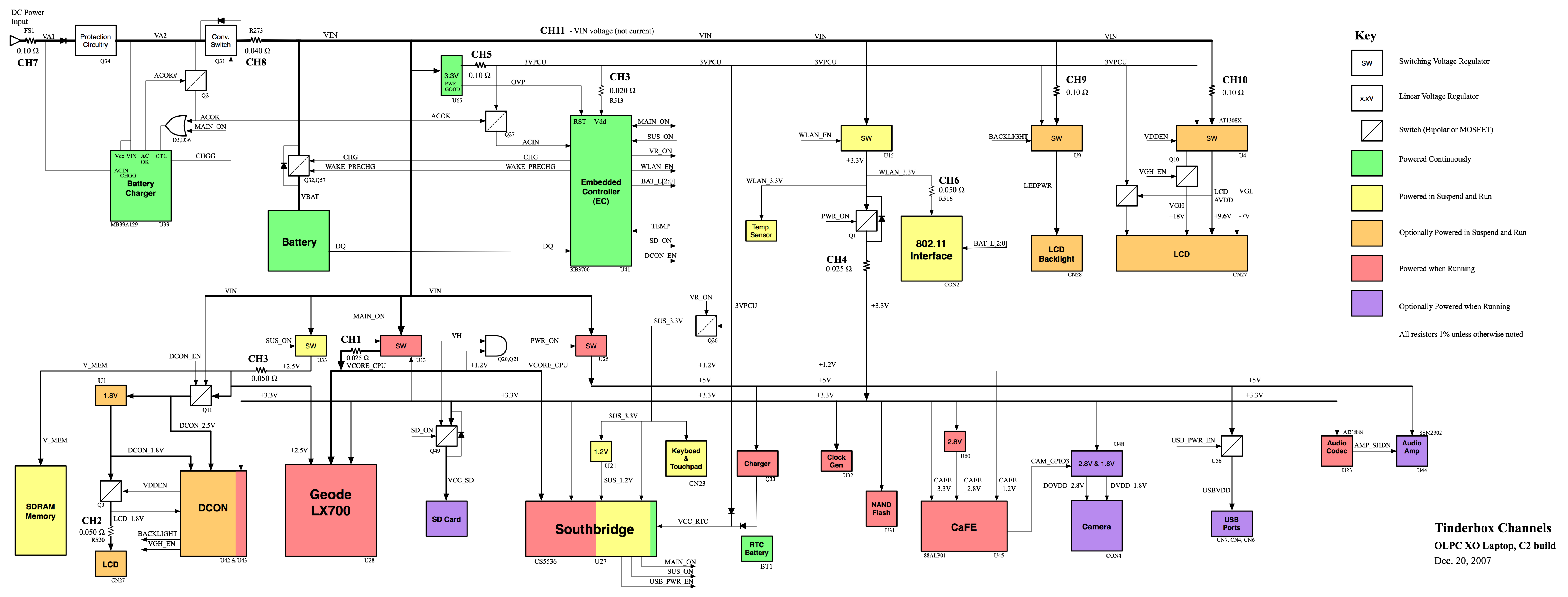
This is power distribution diagram for an XO-1 laptop:
This page is part of the troubleshooting guide and the power management documentation and indicates measurement channels (resistors) not present in production machines. See XO motherboard photo for the location of these blocks.
