XO 1.75 C1: Difference between revisions
(Proper name for Open Firmware) |
|||
| (5 intermediate revisions by one other user not shown) | |||
| Line 4: | Line 4: | ||
== Description == |
== Description == |
||
The C1 are the last prototypes of the [[Hardware# |
The C1 are the last prototypes of the [[Hardware#XO-1.75_Laptop|XO-1.75]] built. Electrically, these are [[XO1.75_B1_C1_Changes#B1_Electrical_Fixes|very similar]] to the [[XO_1.75_B1|B1 prototypes]]. A small number were made in September, 2011, for final testing. |
||
== Identification == |
== Identification == |
||
| Line 12: | Line 12: | ||
While [[Manufacturing_Data#XO-1.75|three version of C1]] were built (SKUs 200, 201, and 202), testing out various alternate component suppliers, from a software and functionality point of view all versions should be identical. Unlike the [[XO_1.75_B1#Description|B1 prototypes]], all C1 laptops provide SDRAM for the [[DCON]]. |
While [[Manufacturing_Data#XO-1.75|three version of C1]] were built (SKUs 200, 201, and 202), testing out various alternate component suppliers, from a software and functionality point of view all versions should be identical. Unlike the [[XO_1.75_B1#Description|B1 prototypes]], all C1 laptops provide SDRAM for the [[DCON]]. |
||
Open Firmware cpu-model OLPC 1C1. |
|||
The motherboard revision is E. |
The motherboard revision is E. |
||
| Line 44: | Line 44: | ||
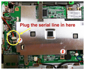
[[Image:1.75_serial_connector.png|thumbnail|Location of serial port]] |
[[Image:1.75_serial_connector.png|thumbnail|Location of serial port]] |
||
Supporting documentation for these boards (all in PDF): |
Supporting documentation for these boards (all in PDF): |
||
* [[XO-1.75|Detailed Specifications]] |
|||
* [[Media:XO_1. |
* [[Media:XO_1.75_Pinouts.pdf|Pinouts]] |
||
* [[Media:XO_1.75_Connectors_B1.pdf|Connector Locations]] |
* [[Media:XO_1.75_Connectors_B1.pdf|Connector Locations]] |
||
* [[Media:XO_1.75_GPIOs_C1.pdf|GPIO Mappings]] |
* [[Media:XO_1.75_GPIOs_C1.pdf|GPIO Mappings]] |
||
* [[Media:XO_1. |
* [[Media:XO_1.75_EC_pinout.pdf|EC Pinout]] |
||
* [[XO_1.75_Power_Distribution|Power Distribution]] |
|||
* Component locations (old): [[Media:XO_1.75_Parts_Bottom_B1.pdf|bottom]], [[Media:XO_1.75_Parts_Top_B1.pdf|top]] |
* Component locations (old): [[Media:XO_1.75_Parts_Bottom_B1.pdf|bottom]], [[Media:XO_1.75_Parts_Top_B1.pdf|top]] |
||
* Unbricking [[SPI_FLASH_Recovery_for_XO-1.75_Using_CForth|using CForth]] and [[SPI_FLASH_Recovery_for_XO-1.75_Using_JTAG|using JTAG]]. |
* Unbricking [[SPI_FLASH_Recovery_for_XO-1.75_Using_CForth|using CForth]] and [[SPI_FLASH_Recovery_for_XO-1.75_Using_JTAG|using JTAG]]. |
||
Latest revision as of 01:27, 7 October 2012
XO-1.75 Laptop C test model 1, also known as C1.
Description
The C1 are the last prototypes of the XO-1.75 built. Electrically, these are very similar to the B1 prototypes. A small number were made in September, 2011, for final testing.
Identification
These are the first XO-1.75 laptops marked as such. XO-1 laptops have a smooth hinge cover, and XO-1.5 laptops have three small raised dots inline on each side of the hinge cover. XO-1.75 laptops have seven small raised dots on the hinge cover, arranged in two rows.
While three version of C1 were built (SKUs 200, 201, and 202), testing out various alternate component suppliers, from a software and functionality point of view all versions should be identical. Unlike the B1 prototypes, all C1 laptops provide SDRAM for the DCON.
Open Firmware cpu-model OLPC 1C1.
The motherboard revision is E.
Photographs:
If you disassemble the laptop (instructions), you will see:
Software
See XO-1.75 software.
Software Restrictions
See XO-1.75 general software restrictions.
See http://dev.laptop.org/1.75 for tickets that are not closed, in the XO-1.75 firmware or software milestones.
Hardware Restrictions
There is a list of recommended modifications (ECOs).
Loss of first character on resume
Unfortunately, we learned too late that the Armada 610 SoC takes a while to wake up from a deep sleep. When a user wakes an XO-1.75 B1/C1 laptop with a keypress, the first key code sent by the keyboard is lost by the SoC (<trac>11401</trac>). This was fixed by having the EC stall the keyboard until the SoC wakes, but requires that resistors be added to the board.
Documentation
Supporting documentation for these boards (all in PDF):
- Detailed Specifications
- Pinouts
- Connector Locations
- GPIO Mappings
- EC Pinout
- Power Distribution
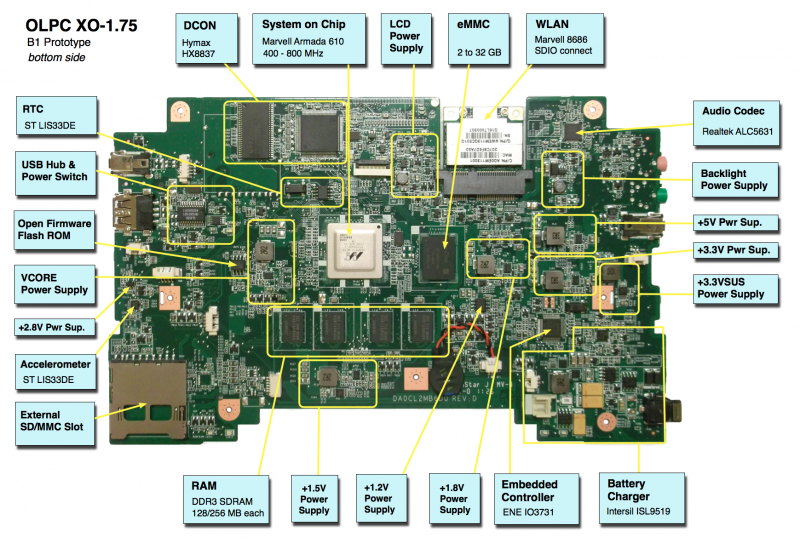
- Component locations (old): bottom, top
- Unbricking using CForth and using JTAG.
- Motherboard photos
Please note that production boards may have different pin mappings and connector locations.

