Adding Bluetooth: Difference between revisions
No edit summary |
mNo edit summary |
||
| (2 intermediate revisions by the same user not shown) | |||
| Line 1: | Line 1: | ||
The [[XO-4]] includes a [[Bluetooth]] adapter function in the wireless card. The remainder of this article is for the [[XO-1]]. --[[User:Quozl|Quozl]] 02:03, 13 August 2013 (UTC). |
|||
| ⚫ | |||
{{outdated}} |
|||
| ⚫ | |||
'''Warning! This modification to your laptop involves both electrical and mechanical changes. Judge for yourself whether you think you have the ability to pull this off successfully.''' |
'''Warning! This modification to your laptop involves both electrical and mechanical changes. Judge for yourself whether you think you have the ability to pull this off successfully.''' |
||
While USB bluetooth devices work fine on the XO (with appropriate |
While USB bluetooth devices work fine on the XO-1 (with appropriate |
||
software changes, which are beyond the scope of this page), it's |
software changes, which are beyond the scope of this page), it's |
||
inconvenient to have a small device always protruding from the |
inconvenient to have a small device always protruding from the |
||
| Line 12: | Line 15: | ||
laptop. After doing so, one of the external USB ports on the XO |
laptop. After doing so, one of the external USB ports on the XO |
||
will no longer be available for "normal" use, and should be |
will no longer be available for "normal" use, and should be |
||
covered or plugged as a reminder. |
covered or plugged as a reminder. |
||
| ⚫ | |||
| ⚫ | |||
| ⚫ | |||
| ⚫ | |||
To get access to the back of the screen assembly, you should |
To get access to the back of the screen assembly, you should |
||
visit and follow the |
visit and follow the instructions for [[Disassembly]]. |
||
You'll need to remove the screen |
You'll need to remove the screen |
||
bezel (i.e. the plastic surrounding on the screen), the screws |
bezel (i.e. the plastic surrounding on the screen), the screws |
||
that hold the screen (but don't disconnect the screen) in order |
that hold the screen (but don't disconnect the screen) in order |
||
to get at the screws behind it that hold on the back -- i.e., the |
to get at the screws behind it that hold on the back -- i.e., the |
||
piece plastic with the |
piece plastic with the logo. (The trick with the screen is to |
||
remove its screws, remove the screws underneath it which old |
remove its screws, remove the screws underneath it which old |
||
the back, then reattach the screen with a couple of screws until |
the back, then reattach the screen with a couple of screws until |
||
| Line 32: | Line 36: | ||
Once you have the back off, you'll see the USB connectors, as in |
Once you have the back off, you'll see the USB connectors, as in |
||
the first picture. I used the top one, which you can see is |
the first picture. I used the top one, which you can see is |
||
labeled CN6. You should |
labeled CN6. You should test this out with an ohmmeter yourself |
||
to verify which pins go where when you plug in your bluetooth |
to verify which pins go where when you plug in your bluetooth |
||
adapter. The plane below (to the left in the picture) of CN6 (on |
adapter. The plane below (to the left in the picture) of CN6 (on |
||
| Line 55: | Line 59: | ||
Unfortunately there's a gap in the pictorial record at this point |
Unfortunately there's a gap in the pictorial record at this point |
||
-- the USB connector has to be removed from the DBT-120 circuit |
-- the USB connector has to be removed from the DBT-120 circuit |
||
board, so that it will fit in the XO. It wasn't particularly |
board, so that it will fit in the XO-1. It wasn't particularly |
||
difficult, but you don't want to make things too hot. I used |
difficult, but you don't want to make things too hot. I used |
||
solder wick to remove most of the solder, then a small pick to |
solder wick to remove most of the solder, then a small pick to |
||
| Line 63: | Line 67: | ||
Some double-sided foam tape holds the bluetooth module to the |
Some double-sided foam tape holds the bluetooth module to the |
||
XO's motherboard. To attach to the ground plane, I used an |
XO-1's motherboard. To attach to the ground plane, I used an |
||
existing contact point near the top edge of the board. To attach |
existing contact point near the top edge of the board. To attach |
||
to the +5 plane, it was necessary to take an sharp knife and |
to the +5 plane, it was necessary to take an sharp knife and |
||
| Line 78: | Line 82: | ||
because the bluetooth module ends up inside of the painted EMI |
because the bluetooth module ends up inside of the painted EMI |
||
shielding of the laptop, the range is cut significantly. Before |
shielding of the laptop, the range is cut significantly. Before |
||
installation, my bluetooth GPS unit could pair with the XO from |
installation, my bluetooth GPS unit could pair with the XO-1 from |
||
up to 25 feet away. Now the limit is about half that. |
up to 25 feet away. Now the limit is about half that. |
||
| Line 88: | Line 92: | ||
that's sturdy enough for |
that's sturdy enough for |
||
the repeated flexing. |
the repeated flexing. |
||
''(the [[XO-4]] Bluetooth uses one of the laptop antennas, and therefore has a much greater range.) --[[User:Quozl|Quozl]] 01:56, 13 August 2013 (UTC)'' |
|||
[[Category:hardware]] |
[[Category:hardware]] |
||
Latest revision as of 02:54, 13 August 2013
The XO-4 includes a Bluetooth adapter function in the wireless card. The remainder of this article is for the XO-1. --Quozl 02:03, 13 August 2013 (UTC).
Installing a Bluetooth adapter into your XO-1
Warning! This modification to your laptop involves both electrical and mechanical changes. Judge for yourself whether you think you have the ability to pull this off successfully.
While USB bluetooth devices work fine on the XO-1 (with appropriate software changes, which are beyond the scope of this page), it's inconvenient to have a small device always protruding from the USB jack.
The basic idea is this: take an off-the-shelf USB bluetooth adapter, take it out of its case, and install it inside the XO laptop. After doing so, one of the external USB ports on the XO will no longer be available for "normal" use, and should be covered or plugged as a reminder.
(As an alternative -if you also consider adding a Touchscreen see: Touchscreen, thus ADDS at least TWO USB-ports!! (user: biopilz))
Open up the XO-1
To get access to the back of the screen assembly, you should visit and follow the instructions for Disassembly. You'll need to remove the screen bezel (i.e. the plastic surrounding on the screen), the screws that hold the screen (but don't disconnect the screen) in order to get at the screws behind it that hold on the back -- i.e., the piece plastic with the logo. (The trick with the screen is to remove its screws, remove the screws underneath it which old the back, then reattach the screen with a couple of screws until it's time to reassemble. You don't want to overuse the little connector that attaches the LCD cable to the motherboard -- it's fragile.)
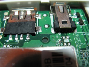
Once you have the back off, you'll see the USB connectors, as in the first picture. I used the top one, which you can see is labeled CN6. You should test this out with an ohmmeter yourself to verify which pins go where when you plug in your bluetooth adapter. The plane below (to the left in the picture) of CN6 (on which the "CN6" label is silkscreened) is +5V, the plane above (to the right in the picture) is ground. The two traces emerging from below the connector and terminating at pads 1 and 4 of L1 are the two USB data lines.
Prepare the transplant
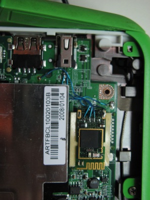
The second picture shows the bluetooth module I used -- a D-Link DBT-120. The case snaps together -- just pry the halves apart gently. Picture #3 shows the result.
Unfortunately there's a gap in the pictorial record at this point -- the USB connector has to be removed from the DBT-120 circuit board, so that it will fit in the XO-1. It wasn't particularly difficult, but you don't want to make things too hot. I used solder wick to remove most of the solder, then a small pick to lift the tabs that hold the connector on, one by one.
Ready for reassembly
Some double-sided foam tape holds the bluetooth module to the XO-1's motherboard. To attach to the ground plane, I used an existing contact point near the top edge of the board. To attach to the +5 plane, it was necessary to take an sharp knife and scrape off a small patch of the green solder resistant layer. (Again, I'm sorry there aren't more pictures.)
Post-op
The results are good -- bluetooth works well. Unfortunately, because the bluetooth module ends up inside of the painted EMI shielding of the laptop, the range is cut significantly. Before installation, my bluetooth GPS unit could pair with the XO-1 from up to 25 feet away. Now the limit is about half that.
It would probably be possible to improve this by mounting the module under the white plastic (on top of the battery). That area of the plastic shell isn't shielded. The difficulty is that the USB connection to the bluetooth module would then need to run through the hinge. This isn't hard to do -- but a cable should be used that's sturdy enough for the repeated flexing.
(the XO-4 Bluetooth uses one of the laptop antennas, and therefore has a much greater range.) --Quozl 01:56, 13 August 2013 (UTC)


