XO1.5 Power ECO: Difference between revisions
No edit summary |
|||
| (7 intermediate revisions by one other user not shown) | |||
| Line 1: | Line 1: | ||
{{outdated}} |
|||
=Scope= |
=Scope= |
||
| Line 4: | Line 5: | ||
This only applies to XO-1.5 [[XO_1.5_B2|B2 phase]] motherboards. |
This only applies to XO-1.5 [[XO_1.5_B2|B2 phase]] motherboards. |
||
'''This solution is flawed, and is superseded by another. Will document ASAP.''' |
|||
==Problem Description== |
==Problem Description== |
||
[[Image:CL1B_A2_LoadLine.png|300px|right]] |
[[Image:CL1B_A2_LoadLine.png|300px|right]] |
||
The result is that if you ''heavily'' load the machine ''and'' throw in a completely discharged battery then the B2 XO 1.5 will pull close to 34W. |
The result is that if you ''heavily'' load the machine ''and'' throw in a completely discharged battery then the B2 XO 1.5 will pull close to 34W. Firmware more recent than Q3A15 should limit this power draw to 29W. |
||
If you try this with on 17W XO-1 adapter bad things happen. At best the overload shutoff kicks in and turns off the adapter but at worst it seems to be possible to run the XO-1 adapter hard for long enough that it fails. The black prototype power supplies that were shipped with the B2's are plenty beefy enough to handle the XO 1.5 B2's so no worries there. |
If you try this with on 17W XO-1 adapter bad things happen. At best the overload shutoff kicks in and turns off the adapter but at worst it seems to be possible to run the XO-1 adapter hard for long enough that it fails. The black prototype power supplies that were shipped with the B2's are plenty beefy enough to handle the XO 1.5 B2's so no worries there. |
||
| Line 16: | Line 19: | ||
=Procedure= |
=Procedure= |
||
The following resistors need their values changed. All resistors are SMD0402, and located on the "bottom" side around PU12. |
The following resistors need their values changed. All resistors are SMD0402, 1%, and located on the "bottom" side around PU12 (the MB39A129 battery charger controller). |
||
# Change PR116 to 270K |
# Change PR116 to 270K |
||
# Change PR117 to 15K. ''On a B2, this resistor (and PR120) appear to be unlabelled. They are located immediately below PQ37 and PQ40 (to which they are attached).'' |
|||
# Change PR117 to 15K |
|||
# Change PR120 to 15K |
# Change PR120 to 15K |
||
# Change PR144 to 560K |
# Change PR144 to 560K |
||
# Change PR125 to 22K |
# Change PR125 to 22K |
||
The load lines resulting from |
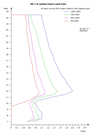
The load lines resulting from a slightly different version are shown in the bottom image on the right.[[Image:CL1B_B2_LoadLine.png|300px|right]]. This version differed in that PR144 was 510K and PR126 was 110K, limiting the peak power. |
||
==Testing== |
==Testing== |
||
You can test the operation of the PWM control circuit using [[Open Firmware]]. Type the following command to set the value of the power PWM: |
You can test the operation of the PWM control circuit using [[Open Firmware]]. Type the following command to set the value (in hexadecimal, from 0 to FF) of the power PWM: |
||
value fa01 ec! |
value fa01 ec! |
||
Latest revision as of 03:03, 13 August 2013
Scope
This describes a change to early prototypes of the XO-1.5 motherboard. It fixes an error in power draw on DC power input of the B2 (and earlier) prototypes. Boards without this ECO will work fine with the 36W adapters provided with the laptops, but they will cause overheating when used with the 17W XO-1 power adapters.
This only applies to XO-1.5 B2 phase motherboards.
This solution is flawed, and is superseded by another. Will document ASAP.
Problem Description
The result is that if you heavily load the machine and throw in a completely discharged battery then the B2 XO 1.5 will pull close to 34W. Firmware more recent than Q3A15 should limit this power draw to 29W.
If you try this with on 17W XO-1 adapter bad things happen. At best the overload shutoff kicks in and turns off the adapter but at worst it seems to be possible to run the XO-1 adapter hard for long enough that it fails. The black prototype power supplies that were shipped with the B2's are plenty beefy enough to handle the XO 1.5 B2's so no worries there.
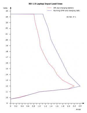
This bug occurred due to some changes wad and Richard made to allow the XO to do MPPT (Maximum Power Point Tracking). This allows the EC to detect that the input power has been exceeded and will dial back the power limit of the charger. This helps when operating on solar panels. The EC in firmware earlier than Q3A16 is constantly enabling maximum power, while the DC input hardware still needs tuning. The load line of a A2 laptop with firmware that doesn't enable maximum power is shown in the top picture to the left.
Procedure
The following resistors need their values changed. All resistors are SMD0402, 1%, and located on the "bottom" side around PU12 (the MB39A129 battery charger controller).
- Change PR116 to 270K
- Change PR117 to 15K. On a B2, this resistor (and PR120) appear to be unlabelled. They are located immediately below PQ37 and PQ40 (to which they are attached).
- Change PR120 to 15K
- Change PR144 to 560K
- Change PR125 to 22K
Testing
You can test the operation of the PWM control circuit using Open Firmware. Type the following command to set the value (in hexadecimal, from 0 to FF) of the power PWM:
value fa01 ec!
For example, to turn off the PWM, type:
0 fa01 ec!
And to set the PWM to constantly on, type:
ff fa01 ec!

