XO 1.5 Motherboard Repair: Difference between revisions
Jump to navigation
Jump to search
No edit summary |
(Added schematics) |
||
| (One intermediate revision by the same user not shown) | |||
| Line 5: | Line 5: | ||
A [[Media:XO_1.5_Repair_Motherboard.pdf|PDF version]] is also available. |
A [[Media:XO_1.5_Repair_Motherboard.pdf|PDF version]] is also available. |
||
There are several production motherboard versions, identified in the silkscreen (white lettering on the motherboard right underneath the VCORE power supply) as rev. G, rev. I, or rev. M. Each has a slightly different schematic: |
|||
* [[Media:XO-1.5_Schematics_rev_G.pdf|Rev. G]] |
|||
* [[Media:XO-1.5_Schematics_rev_I.pdf|Rev. I]] |
|||
* [[Media:XO-1.5_Schematics_rev_M.pdf|Rev. M]] |
|||
Other images of the XO-1.5 electronics include: |
Other images of the XO-1.5 electronics include: |
||
Latest revision as of 03:18, 29 October 2013
This page is monitored by the OLPC team.
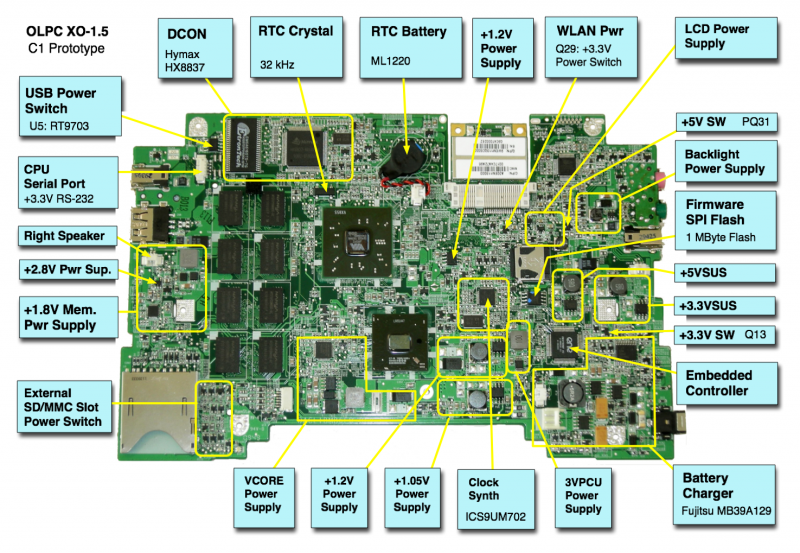
This is the motherboard of a prototype XO 1.5 laptop:
A PDF version is also available.
There are several production motherboard versions, identified in the silkscreen (white lettering on the motherboard right underneath the VCORE power supply) as rev. G, rev. I, or rev. M. Each has a slightly different schematic:
Other images of the XO-1.5 electronics include:
- Annotated photo of motherboard
- Photo of motherboard top
- Photo of motherboard bottom
- SPI Flash location
- SPI Port closeup
- Location of Connectors and Jumpers
This page is part of a larger troubleshooting guide.
