XO 3 Battery: Difference between revisions
m (→Nomenclature) |
|||
| (10 intermediate revisions by the same user not shown) | |||
| Line 1: | Line 1: | ||
{{OLPC}} |
|||
This page contains a discussion of the battery technology for use in the XO-3 tablet. |
This page contains a discussion of the battery technology for use in the [[XO-3]] tablet. |
||
=Introduction= |
=Introduction= |
||
| Line 19: | Line 20: | ||
===Battery Cell Balancing=== |
===Battery Cell Balancing=== |
||
If battery cells are connected in series, differences in cell voltages will cause some cells to receive more power than others when charging. Over a number of charge cycles, this will lead to a charge imbalance between the cells in the battery. This is prevented by matching the voltages of the battery cells used in a battery |
If battery cells are connected in series, differences in cell voltages will cause some cells to receive more power than others when charging. Over a number of charge cycles, this will lead to a charge imbalance between the cells in the battery. This is prevented to some degree by matching the voltages of the battery cells used in a battery when manufacturing them. |
||
A more complex battery charger can independently measure the voltage across each cell in a battery, and independently charge each one in order to rebalance the battery. For an open hardware example of such a battery charger, see [http://www.kosagi.com/w/index.php?title=Novena_Main_Page Bunnie Huang's Novena Battery Board]. |
|||
==Parallel Connection== |
==Parallel Connection== |
||
| Line 33: | Line 36: | ||
=Battery Configuration= |
=Battery Configuration= |
||
Unfortunately, the realities of actual battery packs introduces factors which make 1S''n''P battery configuration less power eficient. The battery charging circuit on the motherboard includes a MOSFET switching transistor for disabling battery charging (Q1) and a low value resistor for measuring the battery charge current (R1). For safety reasons, all Lithium based battery packs include a safety circuit which disconnects the battery in cases of overcurrent, overvoltage or overtemperature. This introduces another current measuring resistor (R2), and two MOSFET switching transistors (Q2/Q3) in series with the battery cells. |
|||
[[Image:XO3_Battery_Reality.png|400px|center]] |
|||
Typical minimum values for these components would be 0.010 ohms for R1 and R2, and 0.030 ohms (drain-source resistance) for Q1, Q2, and Q3, giving a minimum resistance of 0.110 ohms in series with the battery cells. If drawing 6W from a 3V (1S''n''P) battery, 440 mW will be wasted in this circuit. Drawing 6W from a 6V (2S''n''P) battery only wastes 110 mW. As these protective components are applied to the battery packs, not the battery cells, increasing the battery pack voltage by placing cells in series decreases the current (power) lost in these necessary protective and sensing components. |
|||
The efficiency of the voltage converters depends on both their loading and the main power bus voltage. There is little increase in voltage conversion efficiency due to the reduced main power bus voltage. Around one third of the system power goes to low voltage supplies which might improve slightly (they operate around 90% efficiency at 5.5-7.5V --- 2S''n''P). Roughly half the system power goes to supplies which have to boost harder from a 2.7-3.8V supply. And the +3.3V supply will have to be a much more expensive buck/boost design (which can, however, be as efficient as the current cheap supply). |
|||
Given these factors and the importance of power savings to OLPC's mission, '''I propose to use a 2S''n''P configuration for the XO-3 battery'''. This is the same battery configuration as used in the [[Hardware#XO-1_Laptop|XO-1/1.5/1.75 laptop]] design. |
|||
=Battery Technology= |
=Battery Technology= |
||
| Line 41: | Line 53: | ||
The current candidate is Lithium Iron Phosphate (LiFePO4). Slight improvements in energy density are available from a hybrid technology, where additional metals other than Iron are used. |
The current candidate is Lithium Iron Phosphate (LiFePO4). Slight improvements in energy density are available from a hybrid technology, where additional metals other than Iron are used. |
||
[[Category:Hardware]] |
|||
[[Category:XO-3]] |
|||
[[Category:Battery_&_Power]] |
|||
Latest revision as of 23:10, 9 April 2014
This page contains a discussion of the battery technology for use in the XO-3 tablet.
Introduction
Batteries consist of single battery cells which are placed in series (to increase the voltage available from the battery) and/or in parallel (to increase the current available from the battery). There are advantages and disadvantages to both approaches --- which should be used in XO-3 ?
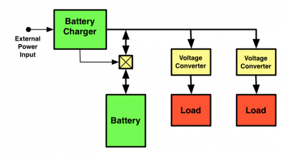
The power distribution network in the XO-3 will have the battery directly connected to the main power distribution bus:
This avoids the inefficiency of converting the battery voltage to the main distribution voltage, but requires that the voltage converters accept the full range of battery voltage.
For LiIon, a single cell ranges from 3.2 to 4.2V (6.4 to 8.4V if 2S1P). For LiFePo4 (used in the XO), a single cell ranges from 2.75 to 3.4V (5.5 to 6.8V if 2S1P).
Series Connection
In this case, two or more battery cells are placed in series to increase the voltage provided by the battery.
- Increases the main system supply voltage, reducing the main supply current and associated losses
- Better match to higher voltage (lower current) external power supplies
Battery Cell Balancing
If battery cells are connected in series, differences in cell voltages will cause some cells to receive more power than others when charging. Over a number of charge cycles, this will lead to a charge imbalance between the cells in the battery. This is prevented to some degree by matching the voltages of the battery cells used in a battery when manufacturing them.
A more complex battery charger can independently measure the voltage across each cell in a battery, and independently charge each one in order to rebalance the battery. For an open hardware example of such a battery charger, see Bunnie Huang's Novena Battery Board.
Parallel Connection
In this case, two or more battery cells are placed in parallel, increasing the total current (capacity) of the battery while keeping the battery voltage equivalent to the cell voltage.
- Avoids cell balancing problems
- Allows a lower system voltage, simplifying charging from a low voltage (USB, or 5V) charger
- Introduces complications in that some power supplies (+3.3V) have to operate from a supply that ranges above and below (2.75V - 3.4V) the desired output.
Nomenclature
Batteries (or battery packs) are referred to by the configuration of the cells internally, using a mSnP naming scheme --- m sets in series of n cells in parallel. Thus a battery which consists of two battery cells in series, none in parallel (such as used in the XO-1) is a 2S1P battery. Actually, the XO-1 battery was designed to be a 2S2P battery, but two oval cells were used in series instead of four cylindrical cells (two sets in series of two cells in parallel) for cost reduction. A typical tablet battery (1S1P or 1S2P) has one or two battery cells in parallel, none in series.
Battery Configuration
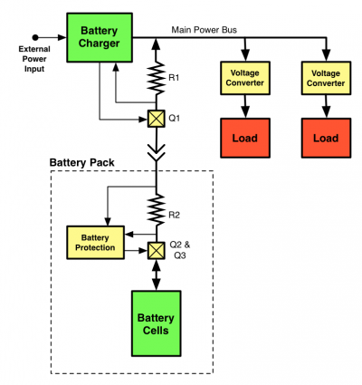
Unfortunately, the realities of actual battery packs introduces factors which make 1SnP battery configuration less power eficient. The battery charging circuit on the motherboard includes a MOSFET switching transistor for disabling battery charging (Q1) and a low value resistor for measuring the battery charge current (R1). For safety reasons, all Lithium based battery packs include a safety circuit which disconnects the battery in cases of overcurrent, overvoltage or overtemperature. This introduces another current measuring resistor (R2), and two MOSFET switching transistors (Q2/Q3) in series with the battery cells.
Typical minimum values for these components would be 0.010 ohms for R1 and R2, and 0.030 ohms (drain-source resistance) for Q1, Q2, and Q3, giving a minimum resistance of 0.110 ohms in series with the battery cells. If drawing 6W from a 3V (1SnP) battery, 440 mW will be wasted in this circuit. Drawing 6W from a 6V (2SnP) battery only wastes 110 mW. As these protective components are applied to the battery packs, not the battery cells, increasing the battery pack voltage by placing cells in series decreases the current (power) lost in these necessary protective and sensing components.
The efficiency of the voltage converters depends on both their loading and the main power bus voltage. There is little increase in voltage conversion efficiency due to the reduced main power bus voltage. Around one third of the system power goes to low voltage supplies which might improve slightly (they operate around 90% efficiency at 5.5-7.5V --- 2SnP). Roughly half the system power goes to supplies which have to boost harder from a 2.7-3.8V supply. And the +3.3V supply will have to be a much more expensive buck/boost design (which can, however, be as efficient as the current cheap supply).
Given these factors and the importance of power savings to OLPC's mission, I propose to use a 2SnP configuration for the XO-3 battery. This is the same battery configuration as used in the XO-1/1.5/1.75 laptop design.
Battery Technology
OLPC is constantly looking for new battery technologies which:
- allow operation and charging over an extended temperature range (0 to 50C)
- are lightweight
- are relatively safe (non-explosive)
The current candidate is Lithium Iron Phosphate (LiFePO4). Slight improvements in energy density are available from a hybrid technology, where additional metals other than Iron are used.

