Serial adapters: Difference between revisions
| (45 intermediate revisions by 4 users not shown) | |||
| Line 1: | Line 1: | ||
Serial connectors are exposed on the XO laptop motherboard, allowing advanced diagnostics. When hooked up to another computer, a serial console allows you to: |
|||
* View firmware messages as the system is booting (even before the display is initialized) |
* View firmware messages as the system is booting (even before the display is initialized) |
||
* Interrupt the booting process at the firmware level and execute forth commands |
* Interrupt the booting process at the firmware level and execute forth commands |
||
| Line 5: | Line 5: | ||
* Access a root shell |
* Access a root shell |
||
A |
A cable and adapter are needed for this. If your development efforts would benefit from having this available, please ask your OLPC technical contact, or ask on the devel@ [[mailing lists|mailing list]]. |
||
Alternatively, you can construct your own adapter from [[#Other_Adapters|adapters made by third-parties]] based on the specifications here. |
|||
= The connectors = |
|||
To access the connectors, you must disassemble the laptop to the point where you can access the top side of the motherboard. See [[Disassembly top]] for instructions. |
|||
= Ingredients = |
|||
Here is what the connector looks like on an XO-1: |
|||
You will need: |
|||
[[Image:Closeup-J1.png]] |
|||
* the laptop being examined, |
|||
* the serial kit, |
|||
* another computer to use as serial console display, with compatible software, and; |
|||
* a safe work space, see [[Disassembly_safety|disassembly safety]] and [[Motherboard Handling Procedures|motherboard handing procedures]], |
|||
= Recipe = |
|||
* [[Disassembly top|disassemble the laptop]] to the point where you can access the component side of the motherboard, |
|||
The [[XO-1]] laptop has two serial ports: |
|||
* [[#Locate the Connectors|locate the connectors]], |
|||
* J1, is a white 4-pin header ([http://wiki.laptop.org/go/File:Closeup-J1.png picture]) located just below the yellow block labelled "+3.3V Supply" on the photo at [[XO Motherboard]], is connected to the serial console on the AMD CS5536 Southbridge processor, |
|||
* [[#Attach_Cables|attach the cables]], |
|||
* CN24, connected to the embedded controller, is generally not used, and is solder pads with no header connector. |
|||
* [[#Software|configure the software on the other computer]], |
|||
* [[#Reassemble|reassemble the laptop with the cables in place]], |
|||
* turn on the laptop, and; |
|||
* verify the firmware startup messages appear on the other computer. |
|||
= Serial kit = |
|||
[[File:Serial_adapter_3.png|400px|thumb]]The serial kit has: |
|||
The [[XO-1.5]] has a serial port connected to the main processor. The white connector can be found directly to the left of the DCON chip, up and to the left of the RAM (refer to [[XO 1.5 Motherboard]]). The connector is labelled "J4". |
|||
* an adapter, with a USB type B socket at one end, and four header pins at the other, |
|||
* a short 210mm cable with four coloured wires, |
|||
<br style="clear: both" /> |
|||
== Where to get it? == |
|||
Serial kits are available for a small charge from http://iLoveMyXO.com directly from their blog at http://iLoveMyXO.wordpress.com |
|||
See [[Spare Parts]] as well as http://twitter.com/iLoveMyXO for availability announcements. |
|||
You may also use [[#Other_Adapters|other adapters]]. |
|||
= Locate the Connectors = |
|||
See the subsection below for the laptop model. |
|||
Reminder: while the laptop is open, follow the [[Motherboard_Handling_Procedures#ESD|precautions to prevent electrostatic damage]]. |
|||
== XO-4 == |
|||
[[Image:1.75_serial_connector.png|thumb|XO-4 UART 1, is in the same position as XO-1.75 UART 3 was so this photograph applies]] |
|||
The [[XO-4]] has three serial ports: |
|||
* UART 1, CN18, connected to the CPU, has the usual white connector pinout, and is used by CForth and Open Firmware, |
|||
* UART 2, CN23, connected to the CPU, is usually not populated, is used by CForth and potentially for kernel debugging, |
|||
* CN19, under the heat spreader, connected to the embedded controller, has the usual white connector pinout, is used by the EC firmware only. |
|||
The XO-4 has two additional serial ports that are not available for use: |
|||
* UART 3, is not configured<!-- per MFPR --> and has no connector,<!-- (C1: TP59, TP113) --> |
|||
* UART 4, is connected to the touchscreen controller for reprogramming. |
|||
<br style="clear: both" /> |
|||
== XO-1.75 == |
== XO-1.75 == |
||
The [[XO-1.75]] has five serial ports: |
|||
[[Image:1.75_serial_connector.png|thumb|XO-1.75 UART 3]] |
[[Image:1.75_serial_connector.png|thumb|XO-1.75 UART 3]] |
||
The [[XO-1.75]] has five serial ports: |
|||
* UART 1, is connected to the CPU, has a difficult to access pinout on a diagnostics port, is generally not used, |
* UART 1, is connected to the CPU, has a difficult to access pinout on a diagnostics port, is generally not used, |
||
* UART 2, is not connected, |
* UART 2, is not connected, |
||
| Line 35: | Line 73: | ||
* UART 4, CN23, connected to the CPU, has the usual white connector pinout, is used by CForth and potentially for kernel debugging, |
* UART 4, CN23, connected to the CPU, has the usual white connector pinout, is used by CForth and potentially for kernel debugging, |
||
* CN14 connected to the embedded controller, has the usual white connector pinout, is used by the EC firmware only. |
* CN14 connected to the embedded controller, has the usual white connector pinout, is used by the EC firmware only. |
||
<br style="clear: both" /> |
|||
== XO- |
== XO-1.5 == |
||
[[Image:XO-1.5-B2-REV-D-J4-with-four-pin-cable.jpg|thumb|XO-1.5 J4 Close-up]] |
|||
The [[XO-4]] has three serial ports: |
|||
[[Image:1. |
[[Image:XO-1.5-B2-REV-D-J1.jpg|thumb|XO-1.5 J1 Close-up]] |
||
* UART 1, CN23, connected to the CPU, has the usual white connector pinout, and is used by CForth and Open Firmware, |
|||
* UART 2, CN18, connected to the CPU, is usually not populated, is used by CForth and potentially for kernel debugging, |
|||
* CN19, under the heat spreader, connected to the embedded controller, has the usual white connector pinout, is used by the EC firmware only. |
|||
The XO- |
The [[XO-1.5]] laptop has two serial ports: |
||
* J4, connected to the CPU, is a white 4-pin header at the top left of the motherboard near a USB socket and the DCON RAM chip. Note: plug it in before turning on the laptop, see [[#XO-1.5_Caveats|XO-1.5 Caveats]] below. |
|||
* UART 3, is not configured<!-- per MFPR --> and has no connector,<!-- (C1: TP59, TP113) --> |
|||
* |
* J1, connected to the embedded controller, is generally not used, and is solder pads with no header connector. |
||
<br style="clear: both" /> |
|||
== XO-1 == |
|||
[[Image:Closeup-J1.png|thumb|XO-1 J1 Close-up]] |
|||
[[Image:Xo-1-c2-j1-plus-cable.jpg|thumb|XO-1 with cable to J1]] |
|||
The [[XO-1]] laptop has two serial ports: |
|||
* J1, is a white 4-pin header ([http://wiki.laptop.org/go/File:Closeup-J1.png picture]) located just below the yellow block labelled "+3.3V Supply" on the photo at [[XO Motherboard]], is connected to the serial console on the AMD CS5536 Southbridge processor, |
|||
* CN24, connected to the embedded controller, is generally not used, and is solder pads with no header connector. A connector can be added, see [[Media:XO-1-C2-REV-J-CN24-with-four-pin-cable.jpg|photograph]]. |
|||
<br style="clear: both" /> |
|||
= Attach Cables = |
|||
The small white end of the cable is to be attached to the connector identified above. |
|||
= How do I get one? = |
|||
The large black end of the cable is to be attached to the pins on the adapter. Take care to line up the connector to match the names of the cable colours printed on the adapter. [[File:Serial_adapter_3.png|800px|thumb|3rd generation serial adapter, showing colour annotations and matching cable connector with wires]]<br style="clear: both" /> |
|||
OLPC-ready serial adapters are available for a small charge from http://iLoveMyXO.com directly from their blog at http://iLoveMyXO.wordpress.com |
|||
On the other end of the adapter is a USB type B socket. Use a USB type A to type B cable. These are not provided in the kit, but you can find them at any computer shop, they are the same cables used for USB printers. Connect the other end of the USB cable to the USB port of another computer where you will be performing the diagnosis. The device will then be recognised as a USB-serial port. |
|||
See OLPC's [[Spare Parts]] page as well as http://twitter.com/iLoveMyXO for possible late-breaking availability announcements. |
|||
Reminder: while the laptop is open, follow the [[Motherboard_Handling_Procedures#ESD|precautions to prevent electrostatic damage]]. |
|||
= Connecting up = |
|||
= Avoid Shorting = |
|||
The OLPC serial kit includes a cable which you can connect to the connector identified above. The other end of this cable gets plugged into the serial board (also included in the serial kit). The connector on the serial board is annotated with the colours of the wires - make sure to line the connector up correctly. [[File:Serial_adapter_3.png|800px|thumb|3rd generation serial adapter, showing colour annotations & matching cable connector with wires]]<br style="clear: both" /> |
|||
[[File:Serial_adapter_covered.jpg|400px|right|serial adapter with heatshrink]] |
|||
On the other side of the serial board, you will see a USB B-type connector. Taking a regular USB A-to-B connection cable (not provided by OLPC, but you can find these at any computer shop, they are the same cables typically used for USB printers), connect this board to the USB port of the other computer where you will be performing the diagnosis. The device will then be recognised as a USB-serial port, and you are good to go. |
|||
Take care not to allow contact between the serial adapter circuit board and metal objects. For regular use in a crowded workspace, enclose the adapter in heatshrink. For example, this adapter is enclosed in 20mm diameter yellow, and 13mm diameter clear, so that the indicators D2 and D1 can be seen. |
|||
<br style="clear: both" /> |
|||
= Software = |
= Software = |
||
The |
The serial adapter contains an FT232R chip made by FTDI, and there are drivers for all major operating systems. The serial console can then be operated through any standard terminal application using the following settings: |
||
* 115200 baud |
* 115200 baud |
||
| Line 99: | Line 151: | ||
*if you use an XO as the host, ''screen'' may be missing because it is not included in our builds, you may install it using yum. |
*if you use an XO as the host, ''screen'' may be missing because it is not included in our builds, you may install it using yum. |
||
*''screen'' is configured slightly differently across our builds with respect to the terminate key, ctrl+a \ works on 11.2.0, but not 10.1.3, but ctrl+a K works with both. |
*''screen'' is configured slightly differently across our builds with respect to the terminate key, ctrl+a \ works on 11.2.0, but not 10.1.3, but ctrl+a K works with both. |
||
*some hosts, including XOs with OLPC OS, may have trouble using a serial adapter, see [[/Linux/ModemManager|more detail]]. |
|||
*some hosts, including XOs with recent OLPC OS builds, include a USB modem detector, ''modemmanager'', which opens any newly plugged serial adaptor, configures it for 57600 baud, and transmits AT commands to elicit a response from a modem. This may interfere. Either connect the coloured serial cable after starting screen, or remove ModemManager package, or stop the process, or edit the udev rules to exclude the serial adaptor. |
|||
ATTRS{idVendor}=="0403", ATTRS{idProduct}=="6001", ENV{ID_MM_DEVICE_IGNORE}="1" |
|||
*if you use an XO as the host, with power management enabled, the /dev/ttyUSB0 device may disappear as a result of suspend. This will terminate ''screen''. Either turn off power management, or prevent it from interfering by prefixing the command with ''olpc-nosleep'', or just restart ''screen'' if you can afford to lose output. |
*if you use an XO as the host, with power management enabled, the /dev/ttyUSB0 device may disappear as a result of suspend. This will terminate ''screen''. Either turn off power management, or prevent it from interfering by prefixing the command with ''olpc-nosleep'', or just restart ''screen'' if you can afford to lose output. |
||
*on particularly old systems, the ''ftdi'' driver may be missing and you may need to upgrade the kernel. |
|||
*when you have many serial adapters, it can be difficult to figure out which one is which. Look for device aliases at /dev/serial/by-path or /dev/serial/by-id. The ''by-path'' aliases are quite long, but are unique by USB socket. |
*when you have many serial adapters, it can be difficult to figure out which one is which. Look for device aliases at /dev/serial/by-path or /dev/serial/by-id. The ''by-path'' aliases are quite long, but are unique by USB socket. |
||
An older option is to use ''minicom'', however this adds complex configuration and menus. ''minicom'' is also packaged in major Linux distributions. Run "minicom -s" to configure |
An older option is to use ''minicom'', however this adds complex configuration and menus. ''minicom'' is also packaged in major Linux distributions. Run "minicom -s" to configure it with the settings suggested above. Adjust the device path (e.g. /dev/ttyUSB0). Exit minicom. Then connect the adapter and run "minicom" again. |
||
If you are running minicom on Fedora and get "Device /dev/ttyUSB0 lock failed: Operation not permitted" errors, re-create the /var/lock/lockdev directory -- more info at https://bugzilla.redhat.com/show_bug.cgi?id=722814 . |
If you are running minicom on Fedora and get "Device /dev/ttyUSB0 lock failed: Operation not permitted" errors, re-create the /var/lock/lockdev directory -- more info at https://bugzilla.redhat.com/show_bug.cgi?id=722814 . |
||
Next, move on to [[#Testing|testing]]. |
|||
== Windows == |
== Windows == |
||
Download and install the [http://www.ftdichip.com/Drivers/VCP.htm driver] using the [http://www.ftdichip.com/Support/Documents/InstallGuides.htm instructions] |
Download and install the [http://www.ftdichip.com/Drivers/VCP.htm driver] using the [http://www.ftdichip.com/Support/Documents/InstallGuides.htm instructions]. |
||
The |
The serial adapter will appear as a COM device and can be operated through HyperTerminal, which is included in a standard Windows install. |
||
It is |
It is possible that COM1 and COM2 are already present and that the adapter will appear as a new COM port, COM3 (or above) when connected and the driver is loaded. If so, configure HyperTerminal for this device. |
||
[[Image:Fdti3.JPG]] |
[[Image:Fdti3.JPG]] |
||
Next, move on to [[#Testing|testing]]. |
|||
With the USB adaptor not connected to anything apart from the Windows PC, typing on Hyperterminal should light up one LED, D1 on the adaptor and there will be no echo on the PC screen. Temporarily bridging the Tx and Rx terminals will light up both D1 and D2 and echo text typed on the PC screen. If you can get this far, you know that the adaptor is working and subject to Baud rate etc. it should be able to communicate with the XO. |
|||
[[Image:Fdti4.JPG]] |
|||
Testing the USB adaptor is working, bridge Tx and Rx |
|||
== Macintosh == |
== Macintosh == |
||
| Line 131: | Line 179: | ||
The hardware will appear as /dev/tty.usbserial-SN, where SN is the serial number. |
The hardware will appear as /dev/tty.usbserial-SN, where SN is the serial number. |
||
''screen'' is also included in Mac OS X, and works well. The default |
''screen'' is also included in Mac OS X, and works well. The default settings are adequate, with the exception of the baud rate. To connect, identify the name of the device in /dev, and start ''screen'' like this: |
||
screen /dev/tty.usbserial-A6008ShI 115200 |
screen /dev/tty.usbserial-A6008ShI 115200 |
||
| Line 138: | Line 186: | ||
Use ctrl-a k to kill window, which causes ''screen'' to terminate. |
Use ctrl-a k to kill window, which causes ''screen'' to terminate. |
||
Next, move on to [[#Testing|testing]]. |
|||
== Remote Linux == |
== Remote Linux == |
||
| Line 156: | Line 206: | ||
== Open Firmware == |
== Open Firmware == |
||
See [[Firmware/Serial_Terminal]]. |
See [[Firmware/Serial_Terminal]], then move on to [[#Testing|testing]]. |
||
= Testing = |
|||
= Reassembling the system = |
|||
You may check that the serial adapter, driver and terminal software are working. |
|||
After connecting and testing the serial console, you might want to reassemble the system. If you want to have the serial cable still accessible for quick connection of the serial board, you have a couple of options: |
|||
With the serial adapter connected to the computer running the software, but not connected to anything else, type on the keyboard and watch the adapter; one LED, D1 should blink, and there should be nothing displayed on screen. |
|||
[[Image:Fdti4.JPG|thumb|Testing the adapter is working, bridge TX and RX.]] |
|||
With the TX and RX terminals temporarily connected, using a screwdriver tip, coin, or jumper leads, type on the keyboard and watch the adapter and the screen; both LEDs, D1 and D2, should blink, and what you type should be displayed on the screen. |
|||
If both tests pass, you can have confidence that the host and the serial adapter are ready for use. |
|||
= Reassemble = |
|||
After connecting and testing the serial console, you might want to reassemble the system. If you want to have the serial cable still accessible for quick connection of the serial board, you have a few options: |
|||
== Run it through the side == |
== Run it through the side == |
||
| Line 167: | Line 229: | ||
There are some holes in the white plastic where the green side-bumper normally gets hooked on (directly to the right of the power button and game keys). You can run the cable through here. You will not be able to properly reattach the side-bumper, you can leave it off or attach it loosely at an angle. |
There are some holes in the white plastic where the green side-bumper normally gets hooked on (directly to the right of the power button and game keys). You can run the cable through here. You will not be able to properly reattach the side-bumper, you can leave it off or attach it loosely at an angle. |
||
<br clear="all" /> |
<br clear="all" /> |
||
== Jam it under the back cover == |
== Jam it under the back cover == |
||
| Line 173: | Line 234: | ||
If you look carefully you will see that in some places, the back cover of the laptop does not make as forceful contact with the rest of the laptop in some places. You can run the cable through here. |
If you look carefully you will see that in some places, the back cover of the laptop does not make as forceful contact with the rest of the laptop in some places. You can run the cable through here. |
||
When re-attaching the back cover, you'll have to apply some force and screw it in well. The cable will probably break at some point due the pressure here. However, it |
When re-attaching the back cover, you'll have to apply some force and screw it in well. The cable will probably break at some point due the pressure here. However, it served well on an XO after 2 years. |
||
<br clear="all" /> |
<br clear="all" /> |
||
== Modify the laptop == |
|||
[[Image:Neat_serial_7.jpg|thumb|Socket mounted in plastic]] |
|||
= XO-1.5 caveats = |
|||
If you expect the serial cable to be used frequently, and yet you need a child to be able to use the laptop, you might also [[Neatly_mounting_a_serial_diag_connector|modify the plastic case]]. |
|||
= XO-1.5 Caveats = |
|||
On the XO-1.5, the serial board must be connected before the laptop boots. If it is connected later, it will not work until the laptop is rebooted. |
|||
On the XO-1.5, the adapter must be connected before the laptop boots. If it is connected later, it will not work until the laptop is rebooted. |
|||
On the XO-1.5, the serial port shares resources with the camera. Only one can be used at a time. If the serial board is detected at boot time, it will be used. The via-camera Linux driver attempts to detect that serial is being used and then prevents itself from loading. If this check is not working for some reason, you will see a load of junk on the serial console when the driver loads. |
|||
This is because the serial port shares resources with the camera. Only one can be used at a time. If the adapter is detected at boot time, it will be used. The via-camera Linux driver detects that an adapter is being used and does not load. If this check is not working, you will see random data on the serial console when the driver loads. |
|||
The exclusivity between serial and camera means that using the serial board to diagnose camera issues on the XO-1.5 is not possible. |
|||
This exclusivity between serial port and camera prevents use of a an adapter to diagnose camera issues on the XO-1.5. You can use telnet instead. |
|||
The XO-1.5 requires the 3rd generation serial board detailed below. |
|||
The XO-1.5 requires the 3rd generation adapter. |
|||
= Serial boards = |
|||
= Adapters = |
|||
Unless otherwise stated, OLPC will always ship the most recent serial adapter generation. Details of older devices are only for historical reference. |
|||
Unless otherwise stated, OLPC will always ship the most recent serial adapter generation. |
|||
== Third generation serial adapter == |
|||
The original adapter that came with the XO-1 ´´ATest´´ boards was very simple and only does +3.3V serial to RS232 voltage level conversion. This only works on the XO-1. |
|||
[[Image:Serial 3rd gen.jpg|thumb|Third gen serial adapter]] |
|||
The current generation of serial adapter is USB-only and does not have any jumper for configuration - just connect it up and go. It works on XO-1, XO-1.5, XO-1.75 and XO-4. |
|||
<br clear="all" /> |
<br clear="all" /> |
||
== Second generation serial adapter == |
== Second generation serial adapter == |
||
''(this section is for historical reference only)'' |
|||
<div style="border-top:1px solid #bbb; border-bottom:1px solid #bbb; padding:4px; background-color:#eee; color:#666"> |
|||
[[Image:serialadapter.jpg|thumb|Second gen serial adapter]] |
[[Image:serialadapter.jpg|thumb|Second gen serial adapter]] |
||
| Line 232: | Line 300: | ||
If you are using Mode 1 then the settings for '''J6''' do not make any difference because the '''DB9''' is not used. |
If you are using Mode 1 then the settings for '''J6''' do not make any difference because the '''DB9''' is not used. |
||
</div> |
|||
== Third generation serial adapter == |
|||
== First generation serial adapter == |
|||
''(this section is for historical reference only)'' |
|||
<div style="border-top:1px solid #bbb; border-bottom:1px solid #bbb; padding:4px; background-color:#eee; color:#666"> |
|||
[[Image:serial adapter.jpg|thumb|First gen serial adapter]] |
|||
The original adapter that came with the XO-1 ´´ATest´´ boards was very simple and only does +3.3V serial to RS232 voltage level conversion. It must be supplied 3.3V from the laptop. Of the XO laptop models, this adapter only works on the XO-1, because only the XO-1 supplies 3.3V on pin 1 of the connector. |
|||
There is nothing else about this adapter that is useful, and modern USB adapters are recommended now. |
|||
[[Image:Serial 3rd gen.jpg|thumb|Third gen serial adapter]] |
|||
The current generation of serial adapter is USB-only and does not have any jumper for configuration - just connect it up and go. It supports XO-1, XO-1.5 and XO-1.75. |
|||
<br clear="all" /> |
<br clear="all" /> |
||
</div> |
|||
= Electrical details = |
= Electrical details = |
||
| Line 244: | Line 321: | ||
The signals levels are 0v/3.3volt TTL. |
The signals levels are 0v/3.3volt TTL. |
||
== Pinout == |
|||
== XO Serial Ports - electrical interface == |
|||
The pinout of the serial connector on the laptop is: |
The pinout of the serial connector on the laptop is: |
||
<table border="1" cellspacing="0" cellpadding="2" width="100%" class="wikitable"> |
|||
<table> |
|||
<tr><th>Pin</th><th>Function</th></tr> |
<tr><th>Pin</th><th>Function</th></tr> |
||
<tr><td>1</td><td>varies by model, see below< |
<tr><td>1</td><td>varies by model, see below<br>marked on PCB with white circle near the connector designator.</td> |
||
<tr><td></td><td>marked on PCB with white circle near the connector designator.</td> |
|||
<tr><td>2</td><td>TX transmit serial data</td></tr> |
<tr><td>2</td><td>TX transmit serial data</td></tr> |
||
<tr><td>3</td><td>RX receive serial data</td></tr> |
<tr><td>3</td><td>RX receive serial data</td></tr> |
||
<tr><td>4</td><td> |
<tr><td>4</td><td>GND return<br> |
||
marked with a small number 4.</td></tr> |
|||
</table> |
</table> |
||
=== XO- |
=== XO-4 === |
||
Pin 1 is not connected. |
|||
J1 Pin 1 is +3.3V supply provided by the laptop for use by the serial adapter. |
|||
=== XO-1.75 === |
|||
In addition, the EC serial connector (CN24) has an additional pin (5), used to provide a clock for programming the serial ROM in recovery mode. This pin expects a +3.3V compatible 65 MHz clock signal, if used. The EC serial port may be used for monitoring by connecting a laptop/serial adapter cable to the first four pins of the connector. |
|||
Pin 1 is not connected. |
|||
The Pinout of the EC serial connector is identical to that of J1 except for the extra pin 5. The 4 pin connector works fine when plugged up to the EC serial port if its justified to Pin 1. |
|||
=== XO-1.5 === |
=== XO-1.5 === |
||
| Line 270: | Line 346: | ||
Pin 1 is an input SERIAL_EN to the VX855, used to sense whether a serial adapter is present, and if so enable the serial port and disable the camera. As a result, the camera indicator is lit. |
Pin 1 is an input SERIAL_EN to the VX855, used to sense whether a serial adapter is present, and if so enable the serial port and disable the camera. As a result, the camera indicator is lit. |
||
In Open Firmware use ''enable-serial'' to enable the serial |
In Open Firmware use ''enable-serial'' to enable the serial adapter if either this mechanism doesn't work, or if an adapter is connected after Open Firmware is started. |
||
The mechanism can be tested also by connecting pin 3 (RX) to pin 1 (SERIAL_EN), since RX has a pullup resistor inside the laptop. |
The mechanism can be tested also by connecting pin 3 (RX) to pin 1 (SERIAL_EN), since RX has a pullup resistor inside the laptop. |
||
=== XO-1 |
=== XO-1 === |
||
Pin 1 is +3.3V supply provided by the laptop for use by the serial adapter. |
|||
Pin 1 is not connected. |
|||
=== XO-4 === |
|||
In addition, the EC serial connector (CN24) has an additional pin (5), used to provide a clock for programming the serial ROM in recovery mode. This pin expects a +3.3V compatible 65 MHz clock signal, if used. The EC serial port may be used for monitoring by connecting a serial adapter cable to the first four pins of the connector. |
|||
Pin 1 is not connected. |
|||
The Pinout of the EC serial connector is identical to that of J1 except for the extra pin 5. The 4 pin connector works fine when plugged up to the EC serial port if its justified to Pin 1. See [[Media:XO-1-C2-REV-J-CN24-with-four-pin-cable.jpg|photograph]]. |
|||
== Mechanical == |
|||
== XO Serial Ports - physical interface == |
|||
Both connectors are very close (though not quite identical) to a 1.25 pitch MOLEX picoblade. The latter will fit perfectly. |
Both connectors are very close (though not quite identical) to a 1.25 pitch MOLEX picoblade. The latter will fit perfectly. |
||
| Line 338: | Line 415: | ||
=== Power === |
=== Power === |
||
The device is powered from either the 3.3V from the laptop or by USB. Both may be plugged up at the same time. |
* The 2nd gen device is powered from either the 3.3V from the laptop or by USB. Both may be plugged up at the same time. |
||
* The 3rd gen device is only powered from the USB host. |
|||
=== Schematics and Board Layout === |
=== Schematics and Board Layout === |
||
==== 3nd Generation ==== |
|||
* [[Media:RCAL USB-TTL Converter 761-7577B.pdf]] <br> |
|||
* [[Media:RCAL - OLPC Serial Converter Layout.pdf]] |
|||
==== 2nd Generation ==== |
|||
* [[Media:OLPC_serial.pdf]] <br> |
* [[Media:OLPC_serial.pdf]] <br> |
||
* [[Media:OLPC_serial_layout.pdf]] |
* [[Media:OLPC_serial_layout.pdf]] |
||
* [http://en.forum.laptop.org/viewtopic.php?f=2&t=430&p=533274#p533274 Discussion on OLPCnews forums about unbricking] |
* [http://en.forum.laptop.org/viewtopic.php?f=2&t=430&p=533274#p533274 Discussion on OLPCnews forums about unbricking] |
||
= Other Adapters = |
|||
== Hooking up the second-generation serial adapter == |
|||
Similar adapters are available from third-parties at low cost. Some examples include: |
|||
On an XO-1 C board, the J1 pinout is: 2 - TX serial data, 3 - RX serial data, 4 - common ground. When the adapter_cable that came with my mini-adapter gets plugged into J1, an orangy wire connects to pin 4 (ground). |
|||
* Adafruit [http://www.adafruit.com/products/284 FTDI Friend + extras] |
|||
* Adafruit [http://www.adafruit.com/products/70 FTDI Serial TTL-232 USB Cable] 178cm (but do not use 5V pin) |
|||
* Adafruit [http://www.adafruit.com/products/954 USB to TTL Serial Cable - Debug / Console Cable for Raspberry Pi] 91cm |
|||
* Adafruit [http://www.adafruit.com/products/1588 Bluefruit EZ-Link - Bluetooth Serial Link & Arduino Programmer] |
|||
* DLP EVAL232R (EVAL232R) |
|||
* [https://jim.sh/ftx/ MicroFTX] serial adapter (must add pins) |
|||
* Pololu [http://www.pololu.com/product/391 USB-to-Serial Adapter] (must add pins) |
|||
* Pololu [http://www.pololu.com/product/1308 CP2104 USB-to-Serial Adapter Carrier] (must add pins) |
|||
* Sparkfun [https://www.sparkfun.com/products/9873 FTDI Basic Breakout - 3.3V (DEV-09873)] (has female pin sockets) |
|||
* Sparkfun [https://www.sparkfun.com/products/9716 FTDI Basic Breakout - 5V (DEV-09716)] (but reconfigure the traces for 3.3V) (has female pin sockets) |
|||
* Sparkfun [https://www.sparkfun.com/products/retired/8772 FTDI Basic Breakout - 3.3V (DEV-08772)] (retired product) |
|||
* Sparkfun [https://www.sparkfun.com/products/retired/10009 (DEV-10009)] (retired product) |
|||
* Sparkfun [https://www.sparkfun.com/products/718 FTDI Breakout Board (BOB-00718)] (must add pins) |
|||
* Sparkfun [https://www.sparkfun.com/products/12977 USB to TTL serial cable - 3.3V (CAB-12977)] (has female pin sockets) |
|||
* Sparkfun [https://www.sparkfun.com/products/12577 Bluetooth Modem - BlueSMiRF Silver] WRL-12577 (must add 3.3V supply, must add pins) |
|||
* Sparkfun [https://www.sparkfun.com/products/12576 Bluetooth Mate Silver] WRL-12576 (must add 3.3V supply, must add pins) |
|||
A serial cable is still needed, or experts can tack solder fine wire to pads. |
|||
The other end of my adapter_cable has a male 5-prong plug, whereas the mini-adapter itself has a female 6-wire_socket receptacle. Unless the adapter_cable is correctly plugged in, the mini-adapter setup will not work. |
|||
= See Also = |
|||
Holding the mini-adapter component-side up, at the cable receptacle the PCB markings label the 1st (top) wire_socket as 'GND'. I inserted the plug end of my adapter_cable so that the orangy wire connected to that wire_socket. That let the two data wires in the cable connect to the 4th+5th wire_sockets (labeled TXO and RXI) on the receptacle. Now the serial adapter connection worked. |
|||
* [[Serial adapters/Arduino|How to use an Arduino as a Serial Adapter]] |
|||
* [[Bluetooth/Serial|How to use an XO-4 laptop as a serial console for another XO laptop via a Bluetooth modem]] |
|||
== Third Party Adapters == |
|||
Very similar adapters are readily available at relatively low cost. Some examples include: |
|||
* DLP EVAL232R (EVAL232R) |
|||
* FTDI Basic Breakout (DEV-08772) |
|||
* FTDI Breakout Board (BOB-00718) |
|||
[[Category:Hardware]] |
[[Category:Hardware]] |
||
Latest revision as of 20:45, 21 October 2015
Serial connectors are exposed on the XO laptop motherboard, allowing advanced diagnostics. When hooked up to another computer, a serial console allows you to:
- View firmware messages as the system is booting (even before the display is initialized)
- Interrupt the booting process at the firmware level and execute forth commands
- View kernel messages as Linux is booting (even before the display is initialized)
- Access a root shell
A cable and adapter are needed for this. If your development efforts would benefit from having this available, please ask your OLPC technical contact, or ask on the devel@ mailing list.
Alternatively, you can construct your own adapter from adapters made by third-parties based on the specifications here.
Ingredients
You will need:
- the laptop being examined,
- the serial kit,
- another computer to use as serial console display, with compatible software, and;
- a safe work space, see disassembly safety and motherboard handing procedures,
Recipe
- disassemble the laptop to the point where you can access the component side of the motherboard,
- locate the connectors,
- attach the cables,
- configure the software on the other computer,
- reassemble the laptop with the cables in place,
- turn on the laptop, and;
- verify the firmware startup messages appear on the other computer.
Serial kit

The serial kit has:
- an adapter, with a USB type B socket at one end, and four header pins at the other,
- a short 210mm cable with four coloured wires,
Where to get it?
Serial kits are available for a small charge from http://iLoveMyXO.com directly from their blog at http://iLoveMyXO.wordpress.com
See Spare Parts as well as http://twitter.com/iLoveMyXO for availability announcements.
You may also use other adapters.
Locate the Connectors
See the subsection below for the laptop model.
Reminder: while the laptop is open, follow the precautions to prevent electrostatic damage.
XO-4

The XO-4 has three serial ports:
- UART 1, CN18, connected to the CPU, has the usual white connector pinout, and is used by CForth and Open Firmware,
- UART 2, CN23, connected to the CPU, is usually not populated, is used by CForth and potentially for kernel debugging,
- CN19, under the heat spreader, connected to the embedded controller, has the usual white connector pinout, is used by the EC firmware only.
The XO-4 has two additional serial ports that are not available for use:
- UART 3, is not configured and has no connector,
- UART 4, is connected to the touchscreen controller for reprogramming.
XO-1.75
The XO-1.75 has five serial ports:
- UART 1, is connected to the CPU, has a difficult to access pinout on a diagnostics port, is generally not used,
- UART 2, is not connected,
- UART 3, CN8, connected to the CPU, has the usual white connector pinout, and is used by CForth and Open Firmware,
- UART 4, CN23, connected to the CPU, has the usual white connector pinout, is used by CForth and potentially for kernel debugging,
- CN14 connected to the embedded controller, has the usual white connector pinout, is used by the EC firmware only.
XO-1.5


The XO-1.5 laptop has two serial ports:
- J4, connected to the CPU, is a white 4-pin header at the top left of the motherboard near a USB socket and the DCON RAM chip. Note: plug it in before turning on the laptop, see XO-1.5 Caveats below.
- J1, connected to the embedded controller, is generally not used, and is solder pads with no header connector.
XO-1


The XO-1 laptop has two serial ports:
- J1, is a white 4-pin header (picture) located just below the yellow block labelled "+3.3V Supply" on the photo at XO Motherboard, is connected to the serial console on the AMD CS5536 Southbridge processor,
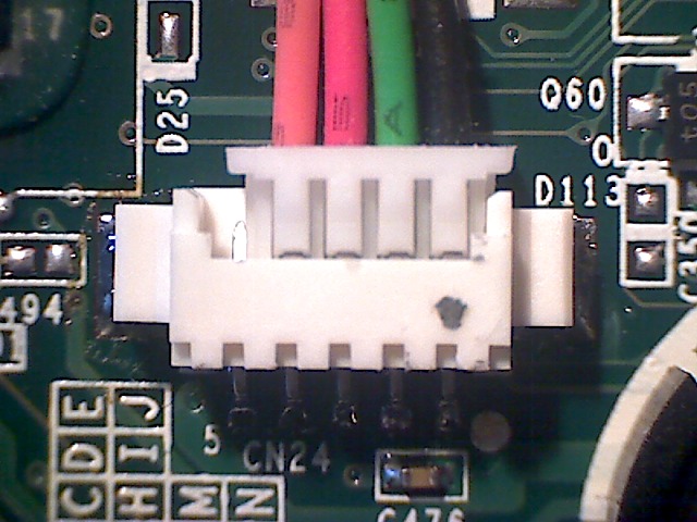
- CN24, connected to the embedded controller, is generally not used, and is solder pads with no header connector. A connector can be added, see photograph.
Attach Cables
The small white end of the cable is to be attached to the connector identified above.
The large black end of the cable is to be attached to the pins on the adapter. Take care to line up the connector to match the names of the cable colours printed on the adapter.
On the other end of the adapter is a USB type B socket. Use a USB type A to type B cable. These are not provided in the kit, but you can find them at any computer shop, they are the same cables used for USB printers. Connect the other end of the USB cable to the USB port of another computer where you will be performing the diagnosis. The device will then be recognised as a USB-serial port.
Reminder: while the laptop is open, follow the precautions to prevent electrostatic damage.
Avoid Shorting

Take care not to allow contact between the serial adapter circuit board and metal objects. For regular use in a crowded workspace, enclose the adapter in heatshrink. For example, this adapter is enclosed in 20mm diameter yellow, and 13mm diameter clear, so that the indicators D2 and D1 can be seen.
Software
The serial adapter contains an FT232R chip made by FTDI, and there are drivers for all major operating systems. The serial console can then be operated through any standard terminal application using the following settings:
- 115200 baud
- 8 data bits
- No parity
- 1 stop bit
- Handshake disabled
- Hardware flow control disabled
- In the USB modes the hardware flow control pins are wired so that they are de-asserted. Therefore the hardware flow control setting does not matter. The RS232 flow control lines on the DB9 were left unconnected and can float such that the flow control is asserted. So in RS232 modes hardware flow control must be disabled.
- Initialization string: none
- Reset string: none
Linux
Plug in the adapter and the kernel will create a device /dev/ttyUSB0, or later.
To connect to the serial console, use screen:
screen -L /dev/ttyUSB0 115200
- the -L flag creates a log file, such as screenlog.0,
- replace /dev/ttyUSB0 with whatever device is appropriate,
- the 115200 specifies the baud rate,
When screen is running:
- what you type is sent to the serial console,
- incoming serial console data is displayed,
Several keyboard shortcuts can be used:
- use ctrl+a ctrl+d to detach from the screen, then to reattach: screen -r,
- use ctrl+a ctrl+b to send a BREAK. Open Firmware responds to a BREAK by interrupting the currently executing code. Linux can be configured to respond to a BREAK.
- use ctrl+a ctrl+a to send a ctrl+a,
- use ctrl+a K to close the screen "window" for the connection and terminate screen.
Some things that might go wrong:
- if you use an XO as the host, screen may be missing because it is not included in our builds, you may install it using yum.
- screen is configured slightly differently across our builds with respect to the terminate key, ctrl+a \ works on 11.2.0, but not 10.1.3, but ctrl+a K works with both.
- some hosts, including XOs with OLPC OS, may have trouble using a serial adapter, see more detail.
- if you use an XO as the host, with power management enabled, the /dev/ttyUSB0 device may disappear as a result of suspend. This will terminate screen. Either turn off power management, or prevent it from interfering by prefixing the command with olpc-nosleep, or just restart screen if you can afford to lose output.
- when you have many serial adapters, it can be difficult to figure out which one is which. Look for device aliases at /dev/serial/by-path or /dev/serial/by-id. The by-path aliases are quite long, but are unique by USB socket.
An older option is to use minicom, however this adds complex configuration and menus. minicom is also packaged in major Linux distributions. Run "minicom -s" to configure it with the settings suggested above. Adjust the device path (e.g. /dev/ttyUSB0). Exit minicom. Then connect the adapter and run "minicom" again.
If you are running minicom on Fedora and get "Device /dev/ttyUSB0 lock failed: Operation not permitted" errors, re-create the /var/lock/lockdev directory -- more info at https://bugzilla.redhat.com/show_bug.cgi?id=722814 .
Next, move on to testing.
Windows
Download and install the driver using the instructions.
The serial adapter will appear as a COM device and can be operated through HyperTerminal, which is included in a standard Windows install.
It is possible that COM1 and COM2 are already present and that the adapter will appear as a new COM port, COM3 (or above) when connected and the driver is loaded. If so, configure HyperTerminal for this device.

Next, move on to testing.
Macintosh
The FTDI driver is not included in Mac OS X. Download and install the driver using the instructions.
The hardware will appear as /dev/tty.usbserial-SN, where SN is the serial number.
screen is also included in Mac OS X, and works well. The default settings are adequate, with the exception of the baud rate. To connect, identify the name of the device in /dev, and start screen like this:
screen /dev/tty.usbserial-A6008ShI 115200
(A6008Shl is the serial number in this example, shell autocomplete makes this unimportant, because you may typically press tab after the letters usb)
Use ctrl-a k to kill window, which causes screen to terminate.
Next, move on to testing.
Remote Linux
How to provide remote serial adapter access to someone on the internet. On the host that has the serial adapter USB side plugged into it:
- install the ser2net package,
- configure /etc/ser2net.conf, deleting unnecessary entries and adding
8097:telnet:0:/dev/ttyUSB0:115200
- start ser2net
service ser2net start
- ssh to some remote host that both people have an account on, using a reverse port forward,
ssh -R 8097:localhost:8097 $REMOTE_HOST
Then tell the other person to type "telnet 0 8097" on that remote host.
Open Firmware
See Firmware/Serial_Terminal, then move on to testing.
Testing
You may check that the serial adapter, driver and terminal software are working.
With the serial adapter connected to the computer running the software, but not connected to anything else, type on the keyboard and watch the adapter; one LED, D1 should blink, and there should be nothing displayed on screen.

With the TX and RX terminals temporarily connected, using a screwdriver tip, coin, or jumper leads, type on the keyboard and watch the adapter and the screen; both LEDs, D1 and D2, should blink, and what you type should be displayed on the screen.
If both tests pass, you can have confidence that the host and the serial adapter are ready for use.
Reassemble
After connecting and testing the serial console, you might want to reassemble the system. If you want to have the serial cable still accessible for quick connection of the serial board, you have a few options:
Run it through the side

There are some holes in the white plastic where the green side-bumper normally gets hooked on (directly to the right of the power button and game keys). You can run the cable through here. You will not be able to properly reattach the side-bumper, you can leave it off or attach it loosely at an angle.
Jam it under the back cover

If you look carefully you will see that in some places, the back cover of the laptop does not make as forceful contact with the rest of the laptop in some places. You can run the cable through here.
When re-attaching the back cover, you'll have to apply some force and screw it in well. The cable will probably break at some point due the pressure here. However, it served well on an XO after 2 years.
Modify the laptop

If you expect the serial cable to be used frequently, and yet you need a child to be able to use the laptop, you might also modify the plastic case.
XO-1.5 Caveats
On the XO-1.5, the adapter must be connected before the laptop boots. If it is connected later, it will not work until the laptop is rebooted.
This is because the serial port shares resources with the camera. Only one can be used at a time. If the adapter is detected at boot time, it will be used. The via-camera Linux driver detects that an adapter is being used and does not load. If this check is not working, you will see random data on the serial console when the driver loads.
This exclusivity between serial port and camera prevents use of a an adapter to diagnose camera issues on the XO-1.5. You can use telnet instead.
The XO-1.5 requires the 3rd generation adapter.
Adapters
Unless otherwise stated, OLPC will always ship the most recent serial adapter generation.
Third generation serial adapter

The current generation of serial adapter is USB-only and does not have any jumper for configuration - just connect it up and go. It works on XO-1, XO-1.5, XO-1.75 and XO-4.
Second generation serial adapter
(this section is for historical reference only)

The second generation adapters are able to do the conversion from LVTTL (3.3V TTL) to RS232 and USB. The also have a mode for converting RS232 to USB. In the RS232 modes they are able to work with both straight and NULL modem cables. Because of this they are a bit more complicated than the first generation adapters. They only work on XO-1.
This complexity is in the form of 2 jumper blocks on the adapters. Blocks J4 and J6.
J4: Mode select block

J4 selects between the 3 modes of operation.
Mode 1: TTL<->USB
- Jumper 1&2, 5&6
Mode 2: RS232<->USB
- Jumper 3&4, 7&8
Mode 3: TTL<->RS232
- Jumper 2&4, 6&8
Note: in the same PCB this conventions are clearly marked
J6: Null Modem block
In the RS232 modes 2 & 3, J6 will swap the TX and RX lines. Normally changing these jumpers is not necessary.
- RS232 NULL Modem: 1&2, 5&6
- RS232 Normal: 3&4, 7&8
To make the adapter appear like a serial port you would find on a PC you would use normal wiring. Connection between the adapter and the PC would use a NULL modem or crossover cable. Just like you would use if you were connecting 2 PC's to each other.
If you are using a serial cable that is wired to be straight through then you would use NULL modem wiring.
If you are using Mode 1 then the settings for J6 do not make any difference because the DB9 is not used.
First generation serial adapter
(this section is for historical reference only)

The original adapter that came with the XO-1 ´´ATest´´ boards was very simple and only does +3.3V serial to RS232 voltage level conversion. It must be supplied 3.3V from the laptop. Of the XO laptop models, this adapter only works on the XO-1, because only the XO-1 supplies 3.3V on pin 1 of the connector.
There is nothing else about this adapter that is useful, and modern USB adapters are recommended now.
Electrical details
If you want to understand more about these connectors or if you want to construct your own serial adapter board, the following information will be of use.
The signals levels are 0v/3.3volt TTL.
Pinout
The pinout of the serial connector on the laptop is:
| Pin | Function |
|---|---|
| 1 | varies by model, see below marked on PCB with white circle near the connector designator. |
| 2 | TX transmit serial data |
| 3 | RX receive serial data |
| 4 | GND return marked with a small number 4. |
XO-4
Pin 1 is not connected.
XO-1.75
Pin 1 is not connected.
XO-1.5
Pin 1 is an input SERIAL_EN to the VX855, used to sense whether a serial adapter is present, and if so enable the serial port and disable the camera. As a result, the camera indicator is lit.
In Open Firmware use enable-serial to enable the serial adapter if either this mechanism doesn't work, or if an adapter is connected after Open Firmware is started.
The mechanism can be tested also by connecting pin 3 (RX) to pin 1 (SERIAL_EN), since RX has a pullup resistor inside the laptop.
XO-1
Pin 1 is +3.3V supply provided by the laptop for use by the serial adapter.
In addition, the EC serial connector (CN24) has an additional pin (5), used to provide a clock for programming the serial ROM in recovery mode. This pin expects a +3.3V compatible 65 MHz clock signal, if used. The EC serial port may be used for monitoring by connecting a serial adapter cable to the first four pins of the connector.
The Pinout of the EC serial connector is identical to that of J1 except for the extra pin 5. The 4 pin connector works fine when plugged up to the EC serial port if its justified to Pin 1. See photograph.
Mechanical
Both connectors are very close (though not quite identical) to a 1.25 pitch MOLEX picoblade. The latter will fit perfectly.
The authoritative drawing for from the manufacturer can be found at File:J1 CN24 male.pdf and File:J1 CN24 female.pdf. The dimensions are listed as CKT 4 for the J1 and CKT 5 for CN21 - both one row.
Generally the plastic connector is sold separate from the metal socket. And you assemble those by crimping a wire to the socket and then inserting it into the connector. The type of socket used requires a special crimping tool.
Some vendors sell ready made 150mm or 300mm cables; with a socket on one and and a tinned lead on the other - which means you can postpone buying the expensive crimp tool for a bit.
Molex numbers
Datasheets: http://www.molex.com/molex/products/datasheet.jsp?part=active/0530470410_PCB_HEADERS.xml (wire to board header) and http://www.molex.com/molex/products/datasheet.jsp?part=active/0510210400_CRIMP_HOUSINGS.xml (terminal and receptacle).
Right angle Molex Pico Blade 1.24 (0.49") PCB 90 degree headers (male, connector) and matching cable sockets (female); SMD is used on the board; the non SMD version can be made to fit and is slightly easier to solder; and much easier to source.
| Connector | pins | board header (male) | receptacle on cable (female) |
|---|---|---|---|
| J1 | 4 | 53048-0410 (non SMD) | 51021-0400 |
| 4 | 53261-0471 (SMD) | 51021-0400 | |
| CN24 | 5 | 53048-0510 (non SMD) | 51021-0500 |
| 5 | 53261-0571 (SMD) | 51021-0500 |
Along with matching sockets (above female connectors are just the 'plastic receptacles'), see item 50125/50133 (http://www.molex.com/catalog/pdf/MX51021.pdf) depending on wire thickness.
Technical drawings of the board socket: http://www.molex.com/pdm_docs/sd/532610271_sd.pdf and for the receptacle http://www.molex.com/pdm_docs/sd/510210400_sd.pdf (J1) or http://www.molex.com/pdm_docs/sd/510210500_sd.pdf (CN24)
Digikey numbers
Equivalent digikey numbers (of above MOLEX-es):
| Connector | pins | board header (male) | receptacle on cable (female) |
|---|---|---|---|
| J1 | 4 | WM7622CT-ND | WM1722-ND |
| CN24 | 5 | WM7623CT-ND | WM1723-ND |
See DigiKey page 1 and DigiKey page 2 for more details.
Depending on the wire thickness - you will need 4 or 5 sockets to wire things up - which have digikey number WM1775-ND (22AW) or WM1142CT-ND (24AQ). The Crimp tools are WM9931-ND, WM9978-ND, WM9932-ND or WM9933-ND depending on the wire.
RS-Component numbers
RS Components only has the receptacles:
| Connector | pins | receptacle on cable (female) |
|---|---|---|
| J1 | 4 | 279-9162 (http://nl.rs-online.com/web/2799162.html) |
| CN24 | 5 | 447-6580(http://nl.rs-online.com/web/4476580.html) |
And a 300mm socket to socket premade wire can be found at # 279-9522 (http://nl.rs-online.com/web/2799522.html) - or alternatively you can order individual sockets and crimp these.
Power
- The 2nd gen device is powered from either the 3.3V from the laptop or by USB. Both may be plugged up at the same time.
- The 3rd gen device is only powered from the USB host.
Schematics and Board Layout
3nd Generation
2nd Generation
Other Adapters
Similar adapters are available from third-parties at low cost. Some examples include:
- Adafruit FTDI Friend + extras
- Adafruit FTDI Serial TTL-232 USB Cable 178cm (but do not use 5V pin)
- Adafruit USB to TTL Serial Cable - Debug / Console Cable for Raspberry Pi 91cm
- Adafruit Bluefruit EZ-Link - Bluetooth Serial Link & Arduino Programmer
- DLP EVAL232R (EVAL232R)
- MicroFTX serial adapter (must add pins)
- Pololu USB-to-Serial Adapter (must add pins)
- Pololu CP2104 USB-to-Serial Adapter Carrier (must add pins)
- Sparkfun FTDI Basic Breakout - 3.3V (DEV-09873) (has female pin sockets)
- Sparkfun FTDI Basic Breakout - 5V (DEV-09716) (but reconfigure the traces for 3.3V) (has female pin sockets)
- Sparkfun FTDI Basic Breakout - 3.3V (DEV-08772) (retired product)
- Sparkfun (DEV-10009) (retired product)
- Sparkfun FTDI Breakout Board (BOB-00718) (must add pins)
- Sparkfun USB to TTL serial cable - 3.3V (CAB-12977) (has female pin sockets)
- Sparkfun Bluetooth Modem - BlueSMiRF Silver WRL-12577 (must add 3.3V supply, must add pins)
- Sparkfun Bluetooth Mate Silver WRL-12576 (must add 3.3V supply, must add pins)
A serial cable is still needed, or experts can tack solder fine wire to pads.