Antenna replacement: Difference between revisions
No edit summary |
No edit summary |
||
| (17 intermediate revisions by 4 users not shown) | |||
| Line 1: | Line 1: | ||
{{draft}} |
|||
{{TOCright}} |
{{TOCright}} |
||
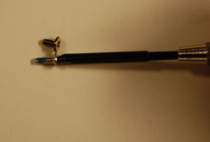
Replacing a wireless antenna is a relatively simple task. To do so, you will need a standard #1 Phillips head screwdriver and something to hold screws in. (In a pinch, parts taken off the XO can serve as temporary containers) This repair can be done within 15 minutes, even with little experience. |
Replacing a wireless antenna is a relatively simple task. To do so, you will need a standard #1 Phillips head screwdriver and something to hold screws in. (In a pinch, parts taken off the XO can serve as temporary containers) This repair can be done within 15 minutes, even with little experience. |
||
<br> |
|||
Click the thumbnails to enlarge them. |
|||
<br> |
|||
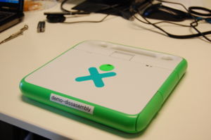
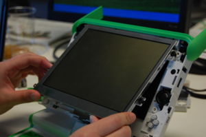
[[image:screen_0.jpg|thumb|left|Before we begin]] |
[[image:screen_0.jpg|thumb|left|Before we begin]] |
||
<br style="clear:both" /> |
<br style="clear:both" /> |
||
== Checking == |
|||
You may check the performance of the old antenna using the [[Antenna_testing|antenna testing procedure]]. This is not essential, but it is helpful if the antenna is being changed because of network connection problems. |
|||
== Taking off the front panel == |
== Taking off the front panel == |
||
| Line 50: | Line 53: | ||
== Removing the |
== Removing the wireless antenna == |
||
=== Step 1 === |
=== Step 1 === |
||
Keep the screen out of the way until the replacement is complete. |
Keep the screen out of the way until the replacement is complete. |
||
[[image:antenna1a.JPG|thumb|left|Take out 4 screws]] [[image:antenna1b.JPG|thumb|left|Turn over. Pull up and remove the back plate]] |
[[image:antenna1a.JPG|thumb|left|Take out 4 screws]] [[image:antenna1b.JPG|thumb|left|Turn over. Pull up and remove the back plate]] |
||
<br style="clear:both" /> |
<br style="clear:both" /> |
||
[[image: |
[[image:Antenna1c.JPG|thumb|left|Take out two screws holding the top bar in place]] [[image:Antenna1d.JPG|thumb|left|Watch out for this tab! Pop it out on both sides]] [[image:Antenna1e.JPG|thumb|left|Pull the top bar off.]] |
||
<br style="clear:both" /> |
|||
=== Step 2 === |
|||
[[image:antenna2a.JPG|thumb|left|Unclip the cable as shown]] [[image:antenna2b.JPG|thumb|left|Peel up the tape.]] |
|||
[[image:Antenna2c.JPG|thumb|left|Remove the two screws.]] |
|||
<br style="clear:both" /> |
|||
[[image:Antenna2d.JPG|thumb|left|Watch out for this tab!]] [[image:Antenna2e.JPG|thumb|left|Carefully pull out the antenna.]] [[image:Antenna2f.JPG|thumb|left|A removed antenna.]] |
|||
<br style="clear:both" /> |
|||
== Replacing the wireless antenna == |
|||
=== Step 1 === |
|||
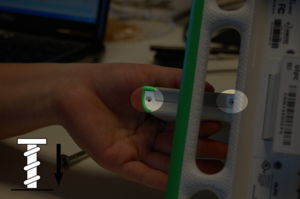
[[image:Antenna3a.JPG|thumb|left|Carefully put in the new wireless antenna]] [[image:Antenna3bi.JPG|thumb|left|Pick the right screw!]] [[image:Antenna3bii.JPG|thumb|left|Screw in the antenna]] |
|||
<br style="clear:both" /> |
|||
=== Step 2 === |
|||
[[image:Antenna3c.JPG|thumb|left|Clip the antenna cable back in.]] [[image:Antenna3d.JPG|thumb|left|Replace the top bar. Do not forget the tabs on the sides! Replace the screws to secure the bar.]] |
|||
<br style="clear:both" /> |
|||
[[image:Antenna3e.JPG|thumb|left|Turn over. Replace the back plate.]] [[image:Antenna3fi.JPG|thumb|left|Pick the right screw!]] [[image:Antenna3fii.JPG|thumb|left|Turn over. Secure the back plate by putting in the four screws where indicated.]] |
|||
<br style="clear:both" /> |
<br style="clear:both" /> |
||
| Line 68: | Line 89: | ||
[[image:Screen_5c.jpg|thumb|left| Gently slide screen back in]] [[image:Screen_5d.jpg|thumb|left| The screws with the large heads (4) go back in]] |
[[image:Screen_5c.jpg|thumb|left| Gently slide screen back in]] [[image:Screen_5d.jpg|thumb|left| The screws with the large heads (4) go back in]] |
||
<br style="clear:both" /> |
<br style="clear:both" /> |
||
(At this point, or later, you may check the performance of the new antenna, using the [[Antenna_testing|antenna testing procedure]].) |
|||
=== Step 2 === |
=== Step 2 === |
||
| Line 86: | Line 109: | ||
And you're done! Yay! :D |
And you're done! Yay! :D |
||
[[Category:Repair]] |
|||
Latest revision as of 08:44, 4 July 2012
Replacing a wireless antenna is a relatively simple task. To do so, you will need a standard #1 Phillips head screwdriver and something to hold screws in. (In a pinch, parts taken off the XO can serve as temporary containers) This repair can be done within 15 minutes, even with little experience.
Click the thumbnails to enlarge them.
Checking
You may check the performance of the old antenna using the antenna testing procedure. This is not essential, but it is helpful if the antenna is being changed because of network connection problems.
Taking off the front panel
Step 1
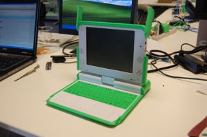
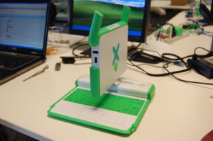
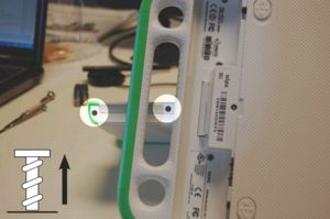
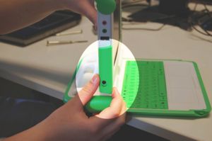
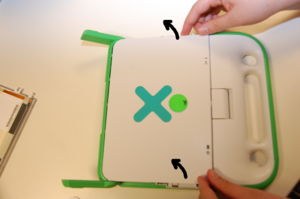
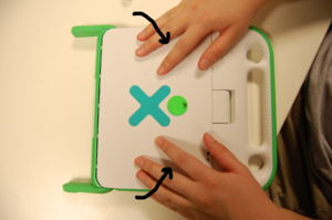
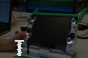
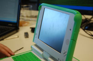
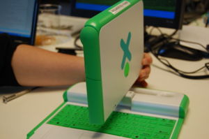
Open the laptop and flip the screen up. Rotate it a 90 degree angle as shown in the sequence below. Next, remove the screws from the bottom of the screen - there are two on each side (right/left) of the XO, so make sure to get all four.
Step 2
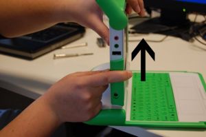
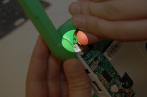
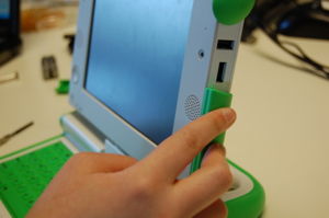
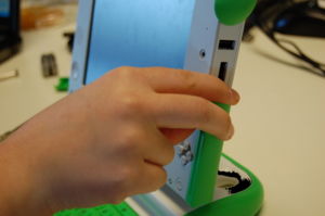
Remove the two green panels from the side of the XO. Slide them upwards and lift them off as shown.
Step 3
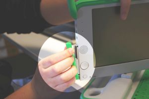
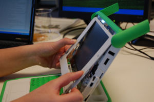
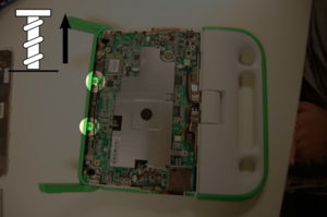
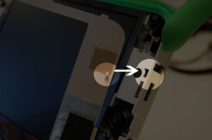
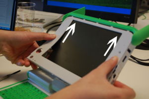
Finally, pull off the front panel. It is tabbed, so it can simply be pulled out. Pull the bottom out (where the screws came out), and gently slide the piece downwards and out.
Taking out the screen
Step 1
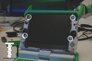
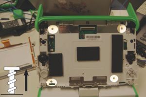
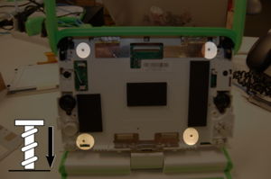
To get the screen out, remove the four screws highlighted.
Step 2
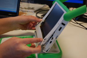
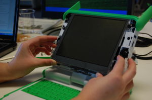
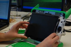
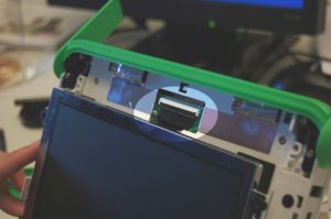
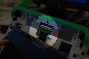
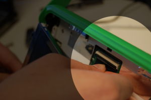
Next, carefully slide the screen out, pulling the bottom out. Do not tug it or let go, as it will still be connected to the motherboard by two cables.
Removing the wireless antenna
Step 1
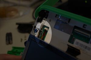
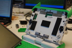
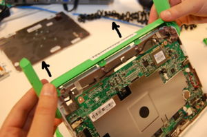
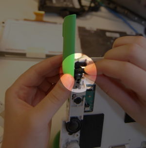
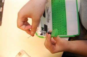
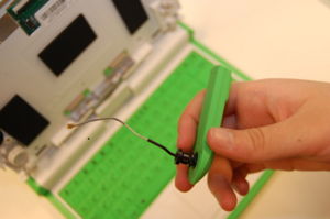
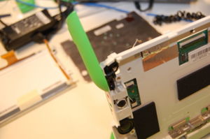
Keep the screen out of the way until the replacement is complete.
Step 2
Replacing the wireless antenna
Step 1
Step 2
Replacing the screen
Step 1
Replace the screen by sliding the connection cables into place and clipping them back down (it is generally easier to clip the thinner one that has a longer tether first). Reseat the screen, making sure that it sits flat and that none of the spacers are gone.
(At this point, or later, you may check the performance of the new antenna, using the antenna testing procedure.)
Step 2
Slide the front panel back on, making sure that it sits flat. Note that there are hooks on the side of the panel (highlighted in blue) that need to slide into place; pushing the top of the screen flat and sliding it upwards works well.
Step 3
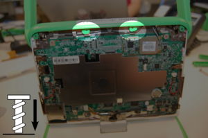
Slide the green side pieces back into place. Then, rotate the XO 90 degrees and put the remaining screws back. Don't forget that the screws go in on both sides (right/left).
And you're done! Yay! :D
