XO 1.5 Motherboard: Difference between revisions
Jump to navigation
Jump to search
No edit summary |
No edit summary |
||
| (4 intermediate revisions by the same user not shown) | |||
| Line 5: | Line 5: | ||
Other images of the XO-1.5 electronics include: |
Other images of the XO-1.5 electronics include: |
||
* [[ |
* [[XO_1.5_Motherboard_Repair|Photo of motherboard annotated for repair]] |
||
* [[Media: |
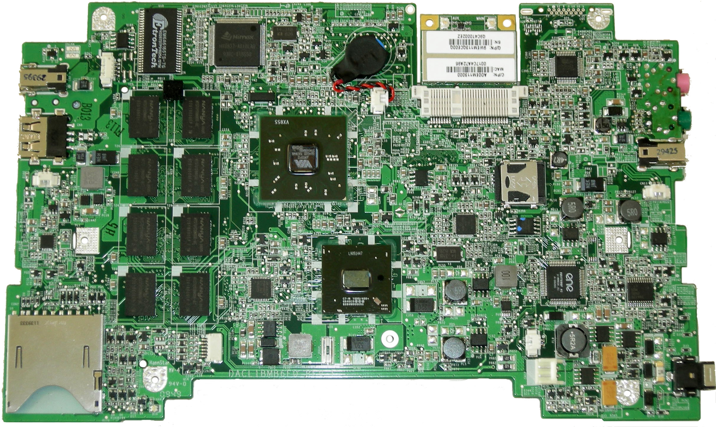
* [[Media:XO-1.5_Motherboard_Top_C1.jpg|Photo of motherboard top]] |
||
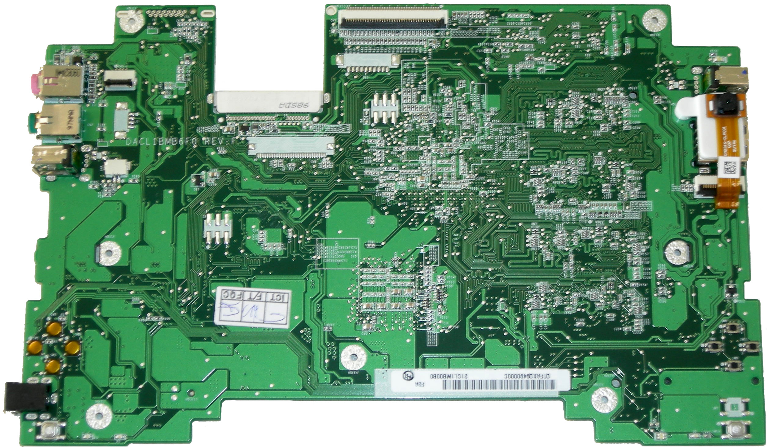
* [[Media:XO-1.5_Motherboard_Bottom_C1.jpg|Photo of motherboard bottom]] |
|||
| ⚫ | |||
* [[ |
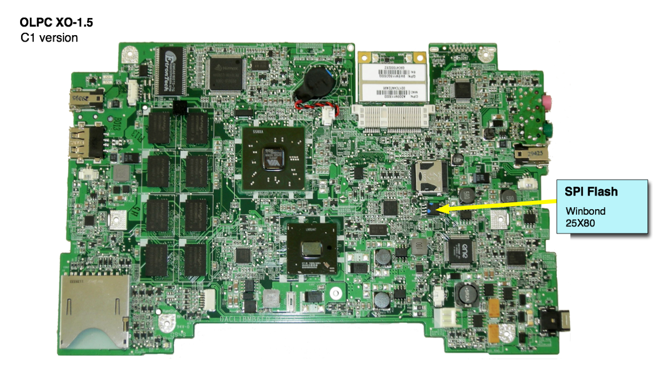
* [[Media:XO1.5_SPI_Flash.png|SPI Flash location]] |
||
| ⚫ | |||
* [[Media:XO_1.5_Connectors_C1.pdf|Location of Connectors and Jumpers]] |
|||
* [[Media:XO1.5_Adapter_Graphic.png|Adapter Graphic (png]], [[Media:XO1.5_Adapter_Graphic.jpg|jpg]] ) |
|||
This page is part of a larger [[XO_Troubleshooting_Guide|troubleshooting guide]]. |
This page is part of a larger [[XO_Troubleshooting_Guide|troubleshooting guide]]. |
||
Latest revision as of 22:33, 12 February 2010
This page is monitored by the OLPC team.
This is the motherboard of a prototype XO 1.5 laptop:

Other images of the XO-1.5 electronics include:
- Photo of motherboard annotated for repair
- Photo of motherboard top
- Photo of motherboard bottom
- SPI Flash location
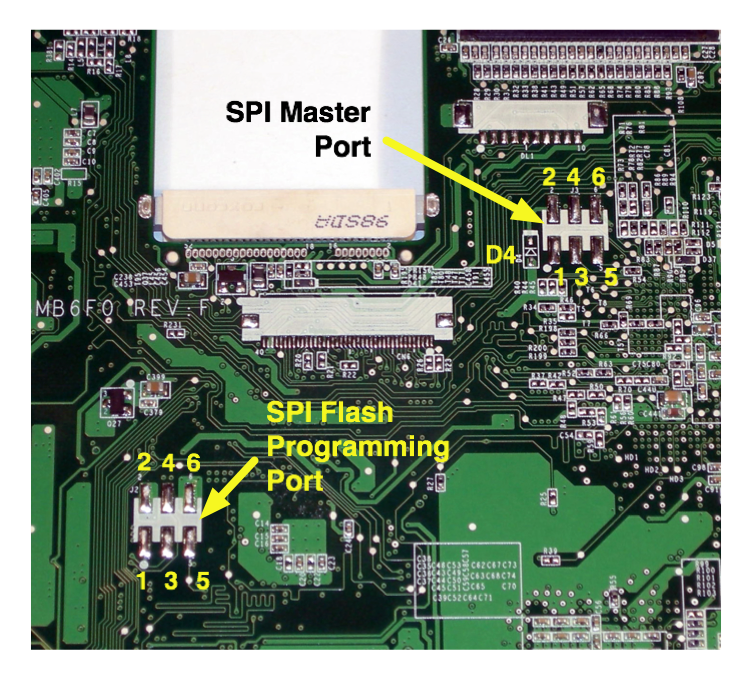
- SPI Port closeup
- Location of Connectors and Jumpers
- Adapter Graphic (png, jpg )
This page is part of a larger troubleshooting guide.