Serial adapters: Difference between revisions
| Line 41: | Line 41: | ||
===Digikey numbers=== |
===Digikey numbers=== |
||
| | pins | board (male) | cable (female) | |
{|| | pins | board (male) | cable (female) || |
||
| J1 | 4 | WM7622CT-ND | WM1722-ND | |
|| J1 | 4 | WM7622CT-ND | WM1722-ND || |
||
| CN24 | 5 | WM7623CT-ND | WM1723-ND | |
|| CN24 | 5 | WM7623CT-ND | WM1723-ND ||} |
||
See [DigiKey page 1|http://dkc3.digikey.com/PDF/T082/P0149.pdf] and [DigiKey page 2|http://dkc3.digikey.com/PDF/T082/P0150.pdf] for more details. |
See [DigiKey page 1|http://dkc3.digikey.com/PDF/T082/P0149.pdf] and [DigiKey page 2|http://dkc3.digikey.com/PDF/T082/P0150.pdf] for more details. |
||
Revision as of 20:02, 26 May 2008
This page contains information about a +3.3V serial/RS-232/USB adapter that is used in low level laptop development.
Hardware
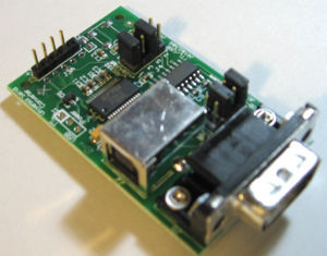
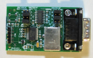
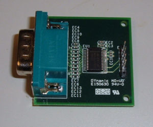
OLPC has two different serial adapters for obtaining serial output from the laptop: the original +3.3Vdc serial/RS-232 level converter that came with the ´´ATest´´ boards, and a new multi-purpose serial adapter which supports +3.3V serial to RS-232 or USB.
XO Serial Ports
The XO laptop has two serial ports provided for low level debugging. One (J1) is connected to the serial console on the main processor (Southbridge, actually). The second (CN24) is connected directly to the embedded controller on the motherboard.
XO Serial Ports - electrical infterface
The pinout of the serial connection on the laptop is: Pin 1. +3.3V is provided by the laptop on this pin, for use by the serial adapter Pin 2. TX serial data Pin 3. RX serial data Pin 4. GND return for both data and power
Pin 1 is marked on PCB with white circle near the J1 designator. Pin 4 is marked with a small number 4.
In addition, the EC serial connector (CN24) has an additional pin (5), used to provide a clock for programming the serial ROM in recovery mode. This pin expects a +3.3V compatible 65 MHz clock signal, if used. The EC serial port may be used for monitoring by connecting a laptop/serial adapter cable to the first four pins of the connector.
The Pinout of the EC serial connector is identical to that of J1 except for the extra pin 5. The 4 pin connector works fine when plugged up to the EC serial port if its justified to Pin 1.
XO Serial Ports - physical infterface
Both connectors are very close (though not quite identical) to a 1.25 pitch MOLEX picoblade. Generally the plastic connector is sold separate from the metal socket. And you assemle those by crimping a wire to the socket and then inserting it into the connector. The type of socket used requires a special crimping tool.
Though most vendors sell ready made 150mm or 300mm cables; with a socket on one and and a tinned lead on the other - which means you can pospone buying the expensive crimp tool for a bit.
Molex numbers
For the right angle Molex Pico Blade 1.24 (0.49") PCB headers (male, connector) and matching cable sockets (female).
|| | pins | board (male) | cable (female) || || J1 | 4 |53048-0410 (non SMD) | 51021-0400 || || J1 | 4 |53261-0471 (SMD) | 51021-0400 || || CN24 | 5 |53048-0510 (non SMD) | 51021-0500 || || CN24 | 5 |53261-0571 (SMD) | 51021-0500 ||
Digikey numbers
| J1 | 4 | WM7622CT-ND | WM1722-ND | CN24 | 5 | WM7623CT-ND | WM1723-ND | }
See [DigiKey page 1|http://dkc3.digikey.com/PDF/T082/P0149.pdf] and [DigiKey page 2|http://dkc3.digikey.com/PDF/T082/P0150.pdf] for more details. Depending on the wire thickness - you will need 4 or 5 sockets - which have digikey number WM1775-ND (22AW) or WM1142CT-ND (24AQ). And the Crimp tools are WM9931-ND WM9978-ND WM9932-ND or WM9933-ND. b RS-Component numbers |
pins | board (male) | cable (female) | | 4 | WM7622CT-ND | 279-916 | | 5 | WM7623CT-ND | 447-6580 |
300mm socket to socket premade wire are # 279-9522. Multipurpose Serial Adapter
This complexity is in the form of 2 jumper blocks on the adapters. Blocks J4 and J6. J4: Mode select blockJ4 selects between the 3 modes of operation. Mode 1: TTL<->USB
Mode 2: RS232<->USB
Mode 3: TTL<->RS232
J6: Null Modem blockIn the RS232 modes 2 & 3, J6 will swap the TX and RX lines. Normally changing these jumpers is not necessary.
To make the adapter appear like a serial port you would find on a PC you would use normal wiring. Connection between the adapter and the PC would use a NULL modem or crossover cable. Just like you would use if you were connecting 2 PC's to each other. If you are using a serial cable that is wired to be straight through then you would use NULL modem wiring. If you are using Mode 1 then the settings for J6 do not make any difference because the DB9 is not used. PowerThe device is powered from either the 3.3V from the laptop or by USB. Both may be plugged up at the same time. Schematics and Board LayoutOriginal Serial AdapterThe original adapter that came with the ´´ATest´´ boards was very simple and only does +3.3V serial to RS232 voltage level conversion.SoftwareThe TTL<->USB chip is a a FT232R made by FTDI and has drivers for all major operating systems. On Windows it will show up as a COMn device and on Linux as a /dev/ttyUSBn device. Where 'n' is a number. On PC systems this will usually start with COM5 and on Linux ttyUSB0. Need some MacOS user to fill in how serial ports work on a Mac DriversWindows and MacOs Linux
Flow ControlIn the USB modes the hardware flow control pins are wired so that they are de-asserted. Therefore the hardware flow control setting does not matter. The RS232 flow control lines on the DB9 were left unconnected and can float such that the flow control is asserted. So in RS232 modes hardware flow control must be disabled. Quirks and Known ProblemsConflict with Braille TTY (brltty) softwareDebian (and derivative) distros come with the brltty package installed. This package conflicts with using the device as a plain serial port. Upon insertion the brltty driver takes over the device and disconnects the /dev/ttyUSBn device. The solution to this is to remove or disable the brltty package. On Debian (and derivatives) you can do this with sudo apt-get remove brltty |


