XO 1.5 USB Keyboard: Difference between revisions
| Line 192: | Line 192: | ||
==Hooking up the USB connection== |
==Hooking up the USB connection== |
||
Ensure that the shield of the USB cable can't short against the motherboard. (Use Kapton tape or heat shrink if necessary). |
Ensure that the shield of the USB cable can't short against the motherboard where it exits from the hinge. (Use Kapton tape or heat shrink if necessary). |
||
{| |
{| |
||
Revision as of 05:26, 6 April 2010
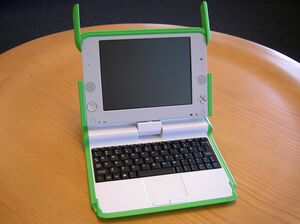
This page describes how to change the keyboard in a XO-1.5 Laptop to a non-membrane USB version.
Scope
These are detailed instructions for installing a non-membrane keyboard into an XO-1.5 laptop. They apply to all pre-production as well as production models. With little change, they also apply to the later model of the XO-1 (with a single capacitive touchpad).
Credit is freely given to the author of the instructions for doing this modification to an XO-1 (part I, II), found on instructables.com.
WARNING
This modification includes permanent modifications of the XO laptop, and cannot be reversed. Even if you are experienced, there is a significant chance of damaging the laptop beyond repair while following these instructions.
Material
You will need:
- An XO-1 (CL1A) or XO-1.5 (CL1B) laptop
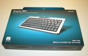
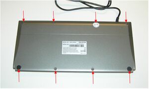
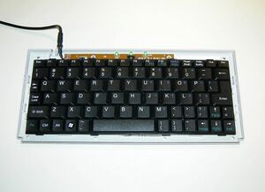
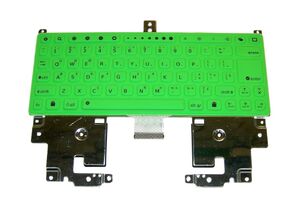
- A micro USB keyboard (such as this one).
- A #1 screwdriver
- Fine pitch soldering equipment
- A magnifier of some sort (lens, loupe, microscope...)
- An X-Acto knife
- A small file and/or fine grade sandpaper
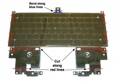
- A way of cutting steel and grinding plastic (such as a Dremel tool)
- cellulose (scotch) or polymide (kapton, preferred) tape
- quick drying epoxy glue or archival double-sided tape
Instructions
Preparing the Keyboard
Dismantling the XO
| Make sure the laptop is running the latest firmware: q2e41 for XO-1 and q3a35 for XO-1.5. | |
| Remove the plastic cover from the hinge between the top and bottom pieces of the XO. There are two screws in the top, holding the two pieces together. | |
| Remove the handle cover. | |
| Disconnect the top and bottom halves of the XO, setting the top unit aside for now. | |
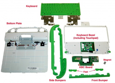
| Completely disassemble the bottom half (leaving only the FPC cable connected to the touchpad --- that connector is incredibly fragile and easy to break.) (link to disass. guide, except missing). | |
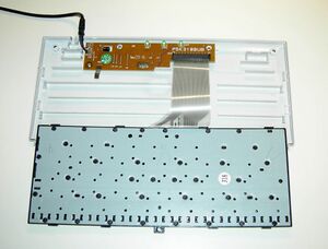
| Remove the keyboard and XO KBC board. | |
|
Remove the waterproofing foam and rubber covering from the KBC controller. Save the rubber. |
Modifying the Keyboard Tray
Modifying the XO Plastic
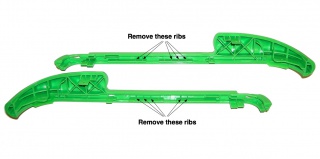
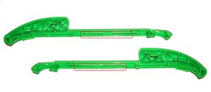
| Remove the spacing flanges from the side bumpers | |
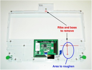
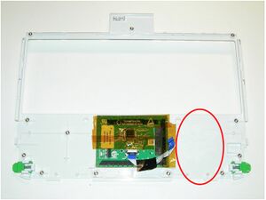
| Remove the right threaded insert on the keyboard bezel/touchpad and surrounding bracing. | |
| Scuff the area where the connector board is going to be glued down. Add electrical insulation to the touchpad - Kapton or electrical tape | |
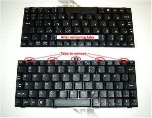
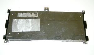
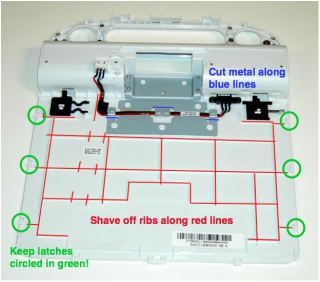
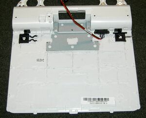
| Take the laptop bottom plate (w. battery compartment) and remove the plastic bracing in the indicated locations | |
Installing the New Keyboard
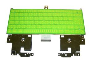
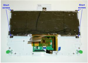
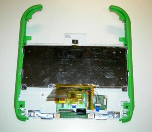
Place the keyboard in the keyboard tray, and attach it to the keyboard bezel. Be careful not to tighten the screws at the top of the tray, as they are missing a spacer. Be careful to only use the short screws for the bottom screws of the tray.
| Now play attention to the vertical fit --- it is a little tight. Gently using a file, it is possible to remove 0.3 to 0.5mm of polycarbonate from the top and bottoms of the keyboard bezel opening, improving the fit. | |
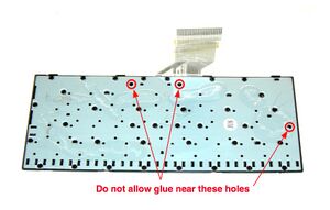
| Once you can get the keyboard located such that no keys rub against the bezel, it is time to secure it. Either epoxy or archival glue can be used. In the case, it is important to reassemble and ensure that the keyboard is centered before it begins to cure. |
Hooking up the Touchpad
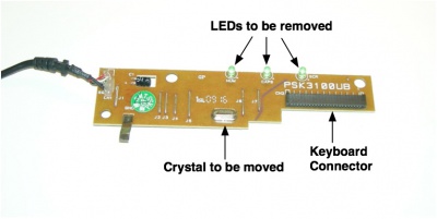
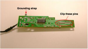
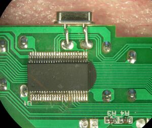
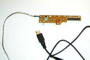
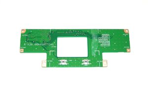
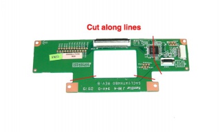
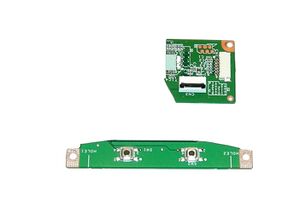
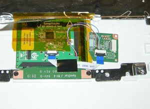
| Remove the KBC chip from the board. Clean the pads, making sure that none are shorting. Cut the KBC board as indicated. | |
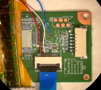
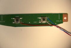
| Check the cut edges of the connector and button boards for layer/layer shorts, shave with XActo as needed to fix. Wire three wires (28/30 ga) between the button board and the connector board. | |
Installing the Connector Board
| Now attach the side bumpers. Make sure to hold the bumpers tight against the keyboard bezel when tightening the screws to ensure a minimal gap. | |
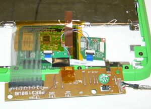
| Place the metal spacers cut from the keyboard, the button board, and the connector board on the keyboard bezel. | |
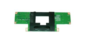
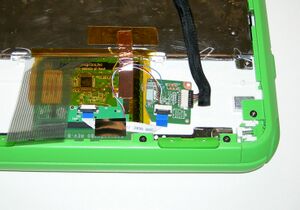
| Using a small amount of epoxy or double-sided tape, secure the connector board to the keyboard bezel. If using epoxy, use cellulose or masking tape to hold it in place while drying. Make sure that you aren't stressing the touchpad cable. Once the epoxy is it is dry, remove the tape. | |
| Reconnect the metal tape between the touchpad grounding pad and the keyboard. Some earlier production models didn't have this tape. Use copper or aluminum tape to bridge the gap. | |
| Attach the cable from the touchpad to the connector board, and reattach the front bumper. | |
| Reconnect the metal tape between the touchpad grounding pad and the keyboard. | |
| Set the keyboard assembly on top of the laptop's top half, and use the "ears" to latch the two together. Attach the KBC cable from the top half to the connector board. | |
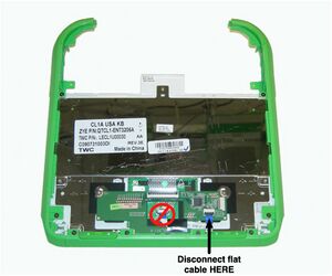
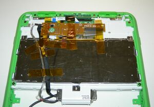
| Connect the keyboard to the USB KBC, if it isn't already. Fold the FPC as shown and use tape to secure the board to the keyboard assembly. |
Route the USB cable right next to the KBC cable, on the side nearest the bumper. Use Kapton or cellulose tape to hold the cables securely in the correct places.
Closing up the Base Assembly
Insert the bottom plate into the laptop. Great force may be necessary! Attach it in place using the two screws into the side bumpers, holding the bumpers tight against the bottom plate when tightening. Reattach the back bumper, using two screws. Hold the bumper up when tightening.
Now is a good time to retest the touchpad/button/keyboard wiring. Plug the USB cable from the USB KBC into the laptop top half. Supply power via a power adapter. Boot the laptop, stopping in OFW by pressing the ESC key when the boot sound starts. Test the touchpad, buttton board, and connector board by typing:
ok test /mouse
| Remove the back panel from the top half of the laptop (this involves removing the front bezel and display). Replace the display and hold it in place with a single screw (for testing). Cut the USB A plug from the end of the USB cable, and route the cable through the laptop hinge. It should emerge next to the existing KBC cable. | |
| Reattach the hinge (and laptop top half) to the base unit using four screws. | |
| Reconnect the battery cable, and place in its holder. Re-route the battery and keyboard cables into their channels. Adjust the slack in the USB cable, routing it above the battery connector! (to avoid having to modify handle cover to avoid pinching the cable) |
Replace the handle cover. Make sure that there is a smooth fit in the front next to the keyboard. Screw it into place with five screws in the battery compartment.
Hooking up the USB connection
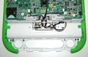
Ensure that the shield of the USB cable can't short against the motherboard where it exits from the hinge. (Use Kapton tape or heat shrink if necessary).
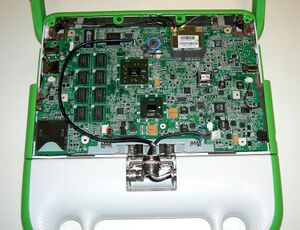
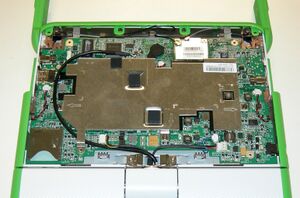
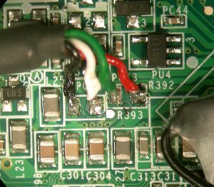
| Remove the heat shield. Route the USB cable around the memory and up to R392/R393 (above the VX855 companion chip). |
Cut the USB cable to length (be generous, there is room for an inch of slack). Remove the cable sheath and shielding. Use Kapton tape, electrical tape, or heat shrink tubing to ensure that there is no way the shielding can short against the motherboard. Strip and tin the four conductors.
| With the motherboard in front of you so that the hinge is closest to you: Solder the red wire to the right-most pad of R392. Solder the black wire to the left-most pad of R393. Solder the green wire to the left-most pad of R392 and the white wire to the right-most pad of R393. |
Closing Up the Laptop
Apply DC power and test the operation of the keyboard and touchpad.
Replace the heat shield, making sure that the cable isn't keeping it from firmly touching the CPU. Remove the display, replace the back plate, and reinstall the display. Reinstall the front bezel, and hinge cover.
