XO1.75 EC Breadboard: Difference between revisions
No edit summary |
No edit summary |
||
| Line 14: | Line 14: | ||
The heart of the breadboard is a ZIF socket for the 0.4 mm pin pitch 128 pin QFP package used by the KB3930. This is part number PA-QFE128SD-C-Z-02W, purchased from [http://www.ironwoodelectronics.com/ Ironwood Electronics]. It includes an adapter PCB, and a wire-wrap adapter attached to that. This was mounted on a piece of 0.1" perfboard, onto which the required connectors and switches were epoxied. |
The heart of the breadboard is a ZIF socket for the 0.4 mm pin pitch 128 pin QFP package used by the KB3930. This is part number PA-QFE128SD-C-Z-02W, purchased from [http://www.ironwoodelectronics.com/ Ironwood Electronics]. It includes an adapter PCB, and a wire-wrap adapter attached to that. This was mounted on a piece of 0.1" perfboard, onto which the required connectors and switches were epoxied. |
||
[[Image:XO1.75_EC_Breadboard_Top.jpg|thumb| |
[[Image:XO1.75_EC_Breadboard_Top.jpg|thumb|220px|center]] |
||
Copper tape was used to supply +3.3V and ground. A sprinkling of 0.1 uF SMD-1206 caps provides decoupling between these. |
Copper tape was used to supply +3.3V and ground. A sprinkling of 0.1 uF SMD-1206 caps provides decoupling between these. |
||
[[Image:XO1.75_EC_Breadboard_Bottom.jpg|thumb| |
[[Image:XO1.75_EC_Breadboard_Bottom.jpg|thumb|300px|center]] |
||
Attaching to the Bonnell development board proved very difficult. I ended up tying to resistor and transistor pads, and a couple of test points, but had to epoxy over the wiring as the pads lifted off the PCB with the slightest force. |
Attaching to the Bonnell development board proved very difficult. I ended up tying to resistor and transistor pads, and a couple of test points, but had to epoxy over the wiring as the pads lifted off the PCB with the slightest force. |
||
[[Image:XO1.75_EC_Breadboard_System.jpg|thumb| |
[[Image:XO1.75_EC_Breadboard_System.jpg|thumb|300px|right]] |
||
Revision as of 04:37, 13 October 2010
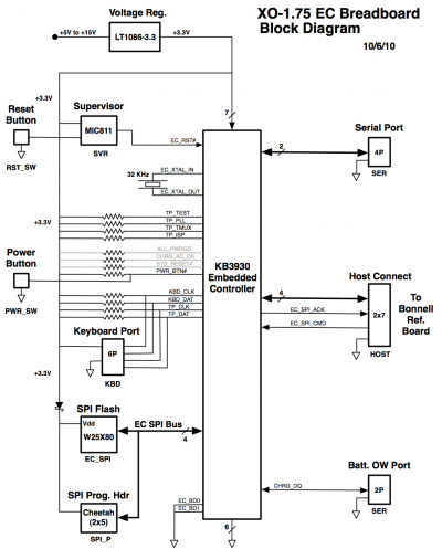
This page describes an engineering prototype used briefly during the bringup of the XO-1.75 design, in order to further software development of the Embedded controller and the XO-1.75 Host/EC communications protocol.
Documentation
The breadboard is powered by any XO power supply.
Construction
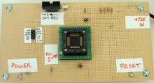
The heart of the breadboard is a ZIF socket for the 0.4 mm pin pitch 128 pin QFP package used by the KB3930. This is part number PA-QFE128SD-C-Z-02W, purchased from Ironwood Electronics. It includes an adapter PCB, and a wire-wrap adapter attached to that. This was mounted on a piece of 0.1" perfboard, onto which the required connectors and switches were epoxied.
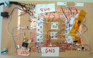
Copper tape was used to supply +3.3V and ground. A sprinkling of 0.1 uF SMD-1206 caps provides decoupling between these.
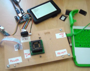
Attaching to the Bonnell development board proved very difficult. I ended up tying to resistor and transistor pads, and a couple of test points, but had to epoxy over the wiring as the pads lifted off the PCB with the slightest force.


