XO1.75 Tinderbox Power: Difference between revisions
(First edit!) |
mNo edit summary |
||
| Line 3: | Line 3: | ||
=Power Distribution= |
=Power Distribution= |
||
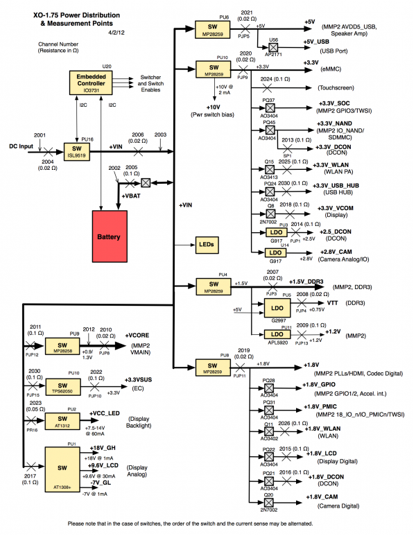
The following diagram attempts to illustrate the XO-1.75 power distribution network, as well as the tinderbox measurement points |
The following diagram attempts to illustrate the [[XO_1.75_Power_Distribution|XO-1.75 power distribution network]], as well as the tinderbox measurement points: |
||
[[Image:XO_1.75_Tinderbox_C2.png|center| |
[[Image:XO_1.75_Tinderbox_C2.png|center|600px]] |
||
=Measurement Points= |
=Measurement Points= |
||
| Line 11: | Line 11: | ||
There are two types of measurement point in the above diagram. Most measure power passing through a particular point in the power distribution network, and are represented by a large X, along with an annotation of the voltmeter channel and measurement resistance. All measurement resistors have a tolerance (variation in resistance) of 1% or smaller. |
There are two types of measurement point in the above diagram. Most measure power passing through a particular point in the power distribution network, and are represented by a large X, along with an annotation of the voltmeter channel and measurement resistance. All measurement resistors have a tolerance (variation in resistance) of 1% or smaller. |
||
A smaller number of points (2001, 2002, 2003) measure the voltage at a particular point in the power network. These are indicated by an arrow, and annotated solely with the voltmeter channel. |
A smaller number of points (2001, 2002, 2003, 2012) measure the voltage at a particular point in the power network. These are indicated by an arrow, and annotated solely with the voltmeter channel. |
||
[[Category:Hardware]] |
[[Category:Hardware]] |
||
Revision as of 03:31, 4 April 2012
This page describes the Tinderbox version of the XO-1.75 C2 laptop.
Power Distribution
The following diagram attempts to illustrate the XO-1.75 power distribution network, as well as the tinderbox measurement points:
Measurement Points
There are two types of measurement point in the above diagram. Most measure power passing through a particular point in the power distribution network, and are represented by a large X, along with an annotation of the voltmeter channel and measurement resistance. All measurement resistors have a tolerance (variation in resistance) of 1% or smaller.
A smaller number of points (2001, 2002, 2003, 2012) measure the voltage at a particular point in the power network. These are indicated by an arrow, and annotated solely with the voltmeter channel.
