B2 Suspend ECR: Difference between revisions
| Line 55: | Line 55: | ||
* SHF70nnn3A0 |
* SHF70nnn3A0 |
||
* PCL10TH70200001 - pre-B2 test sample ("frankenB2"), modified by Mitch Bradley |
* PCL10TH70200001 - pre-B2 test sample ("frankenB2"), modified by Mitch Bradley |
||
* SHF704000A8 |
|||
Some of these serial numbers are incomplete (indicated by nnn digits). Please supply all digits if you know them! |
Some of these serial numbers are incomplete (indicated by nnn digits). Please supply all digits if you know them! |
||
Revision as of 08:32, 30 May 2007
This page describes how to modify an XO B2 laptop to better support suspend/resume.
Keyboard Power
This ECR addresses Trak ticket 895. It changes the power supplied to the keyboard and touchpad so that they are powered in suspend mode. In a B2 unit, the keyboard power comes from +3.3V, which is normally turned off in suspend. This ECR powers the keyboard from the SUS_3.3V supply.
- Disassemble the laptop until the motherboard is exposed (the motherboard does not need to be removed, so the display may remain connected.) Remove the processor heat sink plate.
- Disconnect the cable going to the keyboard (CN23).
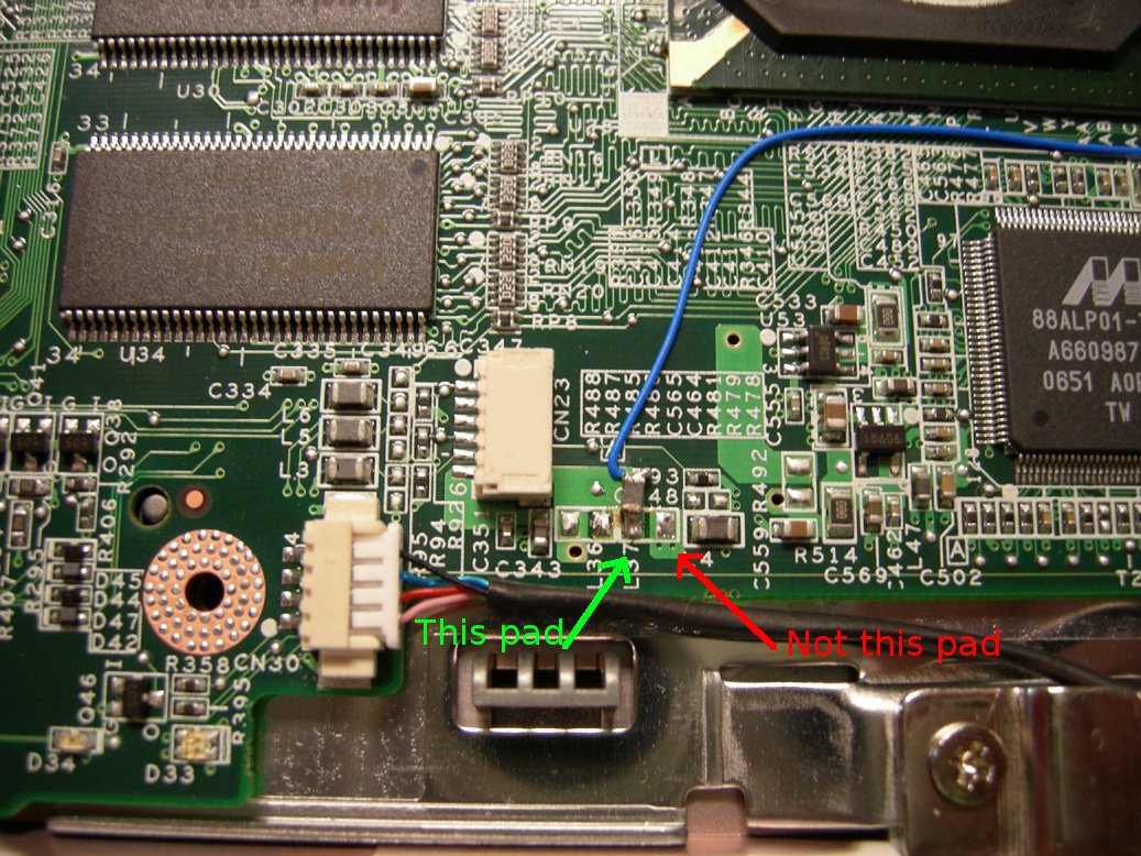
- Rotate L37, an 0805 ferrite located very close to CN23, the keyboard connector, so that it is only connected by one pad (the one wired to L36, a non-populated 0805 adjacent to L37).
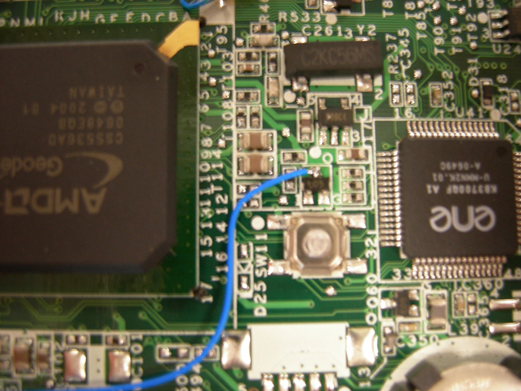
- The other terminal of L37 (resting on the soldermask) should be wired with a blue wire to the center pin of Q26. Q26 is a three lead SOT-23 located halfway between the Southbridge (U27) and the EC (U41), immediately above the EC reset switch. The silkscreen legend identifying Q26 is part of block J, located near SDRAM U22 (nowhere near Q26 !).
- Reconnect the keyboard cable and reassemble the unit.
The use of two soldering irons is strongly recommended. If you damage the ferrite in the removal process, throw it away and solder the blue wire directly to the pad.
Here is a photo of L37, after the ECR has been completed:
Here is a photo of Q26, after the ECR has been completed:
DCONLOAD pulldown
This ECR addresses Trak ticket 947. It changes a pullup on DCONLOAD to be a pulldown instead (see the trak ticket for more description.)
- Disassemble the laptop until the motherboard is exposed (the motherboard does not need to be removed, so the display may remain connected.) Remove the processor heat sink plate.
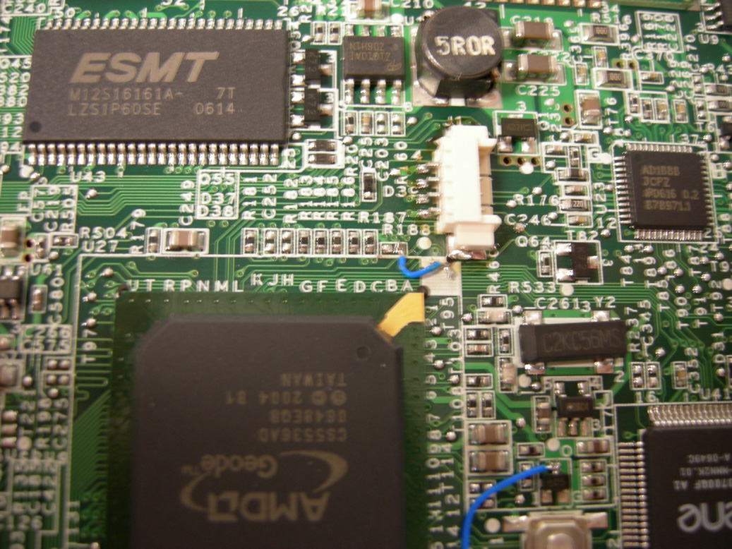
- Remove R188, an 0402 resistor located near the top of the Southbridge (U27) and the serial port connector (J1).
- Place the resistor removed on the silkscreened square next to the lower mounting pad for J1, and solder one terminal to the lower mounting pad for J1 (which is grounded).
- Run a blue wire between the other terminal of the resistor and the closest pad for R188. The other R188 pad (which you should NOT be wiring to) is visibly connected to R187.
- Replace the processor heat sink and reassemble the unit.
Here is a photo of R188, after the ECR has been completed.
Laptops Modified
The following laptops have already been modified, and sent out to developers. We are placing a green sticker labelled "PWR" in the battery compartment of these laptops.
- SHF704000CE
- SHF70500391
- SHF70600283
- SHF70600294
- SHF70600370
- SHF70500219
- SHF70500240
- SHF70500358
- SHF70500341
- SHF70nnn27F
- SHF70nnn34A
- SHF70nnn392
- SHF70nnn3AA
- SHF70nnn3A0
- PCL10TH70200001 - pre-B2 test sample ("frankenB2"), modified by Mitch Bradley
- SHF704000A8
Some of these serial numbers are incomplete (indicated by nnn digits). Please supply all digits if you know them!


