Serial adapters: Difference between revisions
| Line 38: | Line 38: | ||
=== Schematics and Board Layout === |
=== Schematics and Board Layout === |
||
[[Image:OLPC_serial.pdf]] < |
[[Image:OLPC_serial.pdf]] <br> |
||
[[Image:OLPC_serial_layout.pdf]] |
[[Image:OLPC_serial_layout.pdf]] |
||
Revision as of 05:15, 4 October 2007
Hardware
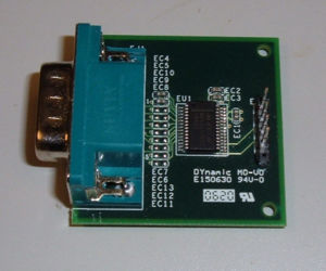
OLPC has 2 different serial adapters for getting serial output from the laptop.
The original adapter that came with the ATest boards
and the new universal adapter [pic_of_new_adapter].
The original ATest adapter is very simple and only does TTL<->RS232.
The new adapters are able to do TTL<->RS232, TTL<->USB, and RS232<->USB. In the RS232 modes they are able to work with both straight and NULL modem cables. Because of this they are a bit more complicated than the ATest adapters.
This complexity is in the form of 2 jumper blocks on the adapters. Blocks J4 and J6.
J4: Mode select block
J4 selects between the 3 modes of operation.
Mode 1: TTL<->USB
- Jumper 1&2, 5&6
Mode 2: RS232<->USB
- Jumper 3&4, 7&8
Mode 3: TTL<->RS232
- Jumper 2&4, 6&8
J6: Null Modem block
In the RS232 modes 2 & 3, J6 will swap the TX and RX lines. Normally changing these jumpers is not necessary.
- RS232 NULL Modem: 1&2, 5&6
- RS232 Normal: 3&4, 7&8
To make the adapter appear a like a serial port you would find on a PC you would use normal wiring. Connection between the adapter and the PC would use a NULL modem or crossover cable. Just like you would use if you were connecting 2 PC's to each other.
If you are using a serial cable that is wired to be straight thru then you would use NULL modem wiring.
If you are using Mode 1 then the settings for J6 do not make any difference because the DB9 is not used.
Flow Control
In the USB modes the hardware flow control pins are wired so that they are de-asserted. Therefore the hardware flow control setting does not matter. The RS232 flow control lines on the DB9 were left unconnected and can float such that the flow control is asserted. So in RS232 modes hardware flow control must be disabled.
