Help Activity refresh/Chapter/Measure
About
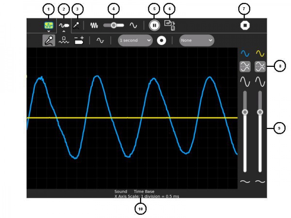
This Activity draws a picture of the sound heard by the laptop microphone or the signal present on the microphone socket. More specifically it draws a graph of this input versus time, the input on the vertical axis, time on the horizontal axis. The laptop functions like a machine called an oscilloscope. As well as graphing signal as a function of time, it can also graph as a function of frequency.
The XO-1 laptop is only capable of mono input, the XO-1.5 and XO-1.75 have stereo input on the microphone socket and can graph two signals at once.
Using
- Select secondary toolbar - allows the Activity's Journal entry to be renamed
- Select secondary toolbar - measurement settings
- The selected input type - Sound (AC voltage), resistance or DC voltage
- The time scale
- Freeze the display
- Capture sample now - saves an image of the wave in the Journal
- Stop - exits the Activity
- Invert - invert the display
- Use these sliders to control the sensitivity
- The settings that are selected
The secondary toolbar - measurement settings 11. Sound - use this setting with the internal microphone, external microphone and external AC signals 12. Resistance sensor - use with external resistive type transducers 13. Voltage sensor - use with external sensors which generate a voltage 14. Time base/frequency - graphs the signal vs. time or graphs the frequency spectrum of the signal 15. Sample interval - a text file 'Measure Log' is saved to the journal, it contains one sample per interval 16. Starts/stops saving a text file 'Measure Log' with measured values as readable text 17. This feature is not working well in version 36, the intention is to synchronise the sample period to the waveform so that the sample will start on a rising edge or falling edge
Applying
Sharing
This Activity does not support sharing.
Extending
Measure is able to take input from a wide range of external sensors including switches, photocells, temperature sensors, inductive loops, hall effect sensors, soil probes and many more.
Care should be taken not to exceed the allowable input voltage:
- XO-1 -0.5V to 5V
- XO-1.5 -6V to +9V
- XO-1.75 -6V to +9V
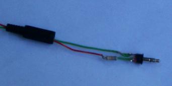
It is a good idea, particularly on the XO-1, to put a resistor of 680 ohms in the phono plug, this increases the allowable input voltage range.
You can find ideas for fun science experiments at http://wiki.sugarlabs.org/go/Activities/TurtleArt/Using_Turtle_Art_Sensors and http://wiki.laptop.org/go/Measure


