Measure/Projects/Lighted Graticule
Lighted Graticule
A graticule is a "scale on transparent material on the focal plane of a optical instrument for the location and measurement of objects" (Webster's Ninth Collegiate Dictionary, 1990, Merriam-Webster Inc, Springfield MA).
The following describes the design of a lighted graticule that works together with a 50:1 (attenuating-) probe (similar to the one described at Measure/Projects/Oscilloscope probe ) to provide the teacher and student with calibrated measurements as displayed on the screen in 1 volt per major division, or 0.10 volt per major division, or 0.010 volt per major division.
Introduction -- Graticule working with 50:1 probe for a calibrated display

Oscilloscopes traditionally light the graticule by illuminating its edges; the graticule material (typically acrylic plastic) "pipes" the light through itself. If the piped light hits a line scratched in the plastic's surface, the light bounces off the scratch and illuminates the line.
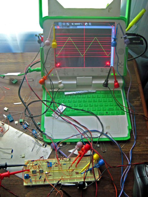
When doing experiments that involve measurements, such lines become almost mandatory. Indeed, I decided I had to breadboard one up (see the photo) in the course of designing a waveform generator. I wanted to make measurements of the extremes of voltage that an LM358A operational amplifier can output when operated from 5 volts. (It turned out to be roughly 0.5 to 3.1 volts just like the spec sheet and calculations indicated.)
At this writing (24 May 2008) the graticule is scribed (scratched deeply) starting in the useable center (measured from 2.00 inches from the bottom) at 0.320 inch intervals up and down from the center, with 1/2 the major interval ruled as a short line. Fortuitously, given a 50:1 attenuation-probe, (i) if the slider is set in the center of the screen (precisely 2.00 inches from the bottom of the screen), and (ii) given that software glitches in "resetting" the display are accounted for [more to follow] then this slider-position corresponds, within +/-1%, to 1.00 volt per major division.
I've experimented with 40:1 attenuation at 0.400 vertical-inch per volt (major division) but have decided that 50:1 attenuation at 0.320 vertical-inch per volt is more useful because 13 as opposed to 9 divisions are possible on the screen (i.e. 6 up from the center, 6 down from the center as opposed to 4 up from the center, 4 down from the center).
The thirteen-division layout provides overlap between the various gain-settings. In other words, a setting of 0.010 volt per division, with the "zero" set to the bottom-most division, will show up to +0.120 volts; a setting of 0.10 volt per division, with the zero set to the bottom-most division, will display up to 1.20 volts, etc. Thus a probe with three user-selectable gains will allow measurements of 1 volt per division or 0.10 volt per division, or 0.010 volt per division. Measurements of 10 volts per division will require a 10:1 attenuator (voltage divider).