This details steps to build a low cost probe for connecting sensors to the XO for use in Measure and other activities that can read sensor input.
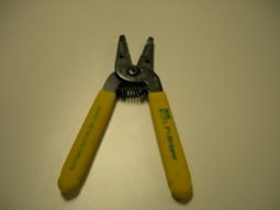
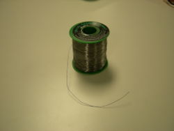
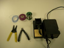 It'd be good to have these tools - A soldering iron, some soldering wire, a wire cutter/wire stripper and some insulating tape |
|
|
|
|
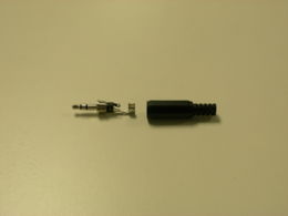
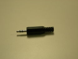 3.5mm audio jack (stereo or mono, any would do) |
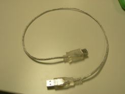 A USB cable, or even a USB connector would do |
|
|
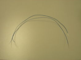
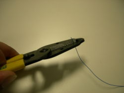 Cut two pieces of wire and strip them at the ends |
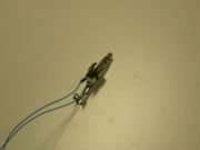 Solder the wires to the connector as shown. Do make sure to have an identification mark (eg. a knot) to differentiate between both the wires.Call the wire connected to the central terminal as "Vin" the wire connected to the outer terminal as "Gnd" |
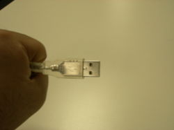 Take the USB cable/connector |
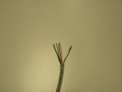 Cut it in the middle and strip the wires |
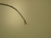 We only need the red and the black wires.The USB port provides us with a source of +5V supply. Let's call the red wire as "+ve" and the black as "Gnd" and make the black one and the "Gnd" defined in audio connector as one, by connecting them together. |
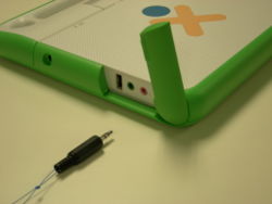 The audio connector goes into the pink MIC input jack |
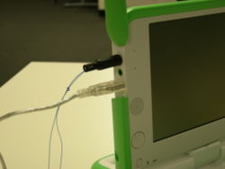 The USB connector goes into the USB port |
To summarize, do remember that we have identified three terminals
- The "Vin" terminal
- The "+ve" terminal
- The "Gnd" terminal (the Gnd of audio connector is connected to Gnd of USB connector"

