Firmware/Serial Terminal
Firmware Serial Terminal
Open Firmware contains a serial terminal emulator that can be used for diagnosis of the laptop, and other laptops.
| command | purpose |
|---|---|
serial
|
connect the keyboard and display to the serial port, use ctrl-a k to exit.
|
serial-log FILE
|
open the FILE, do serial and write all output to the FILE, and close the FILE on exit
|
use-usb
|
set up serial to use a USB serial adapter, the default.
|
use-uart
|
set up serial to use the built-in serial port UART.
|
Using a USB serial adapter
How to use an XO as a serial terminal to another XO, using a USB serial adapter.
You will require:
- an XO to act as host, with a build of Open Firmware after svn 3568,
- a USB serial adapter,
- a USB cable, type A male to type B female,
- an XO to act as target.
Preparation:
- connect the target XO to the USB serial adapter,
- connect the B end of the USB cable to the serial adapter,
- connect the A end of the USB cable to the host XO.
Starting:
- start the program:
ok serial
The program supports some key sequences used by screen:
ctrl+a korctrl+a ctrl+dto exit,ctrl+a ctrl+bto send a break,ctrl+a ctrl+ato send actrl+a,ctrl+a Cto clear the screen.
Logging
How to record a log of the session:
ok serial-log u:\file.log
The log is written to the file file.log on the USB drive.
Using back to back serial ports
How to use an XO as a serial terminal (host) to another XO (target), without using any USB serial adapters:
- on the XO acting as host, get to the Ok prompt, and set up to use the serial port:
ok use-uart
- start the program:
ok serial
- connect a crossover cable,
- turn on the target.
Caution: the use-uart command turns off the Open Firmware serial console, to avoid unpleasant interaction between the Open Firmware ok prompt and any connected device. Connecting the cable before use-uart may result in each laptop screaming at the other repeatedly.
A crossover cable, to join two OLPC-supplied serial cables, consists of the following:
| host pin (cable colour) | target pin (cable colour) | purpose |
|---|---|---|
| GND (orange) | GND (orange) | ground |
| RX (red) | TX (green) | display data, target to host |
| TX (green) | RX (red) | keyboard data, host to target |
The 3.3V (black) pin is not connected.
A crossover cable may also be fabricated from two PCB connectors, or using wire soldered to the connector pads.
Using an XO as a network relay to another XO
See Firmware/Remote#Combining_with_serial_terminal for how to use an XO as a network serial adapter for another XO.
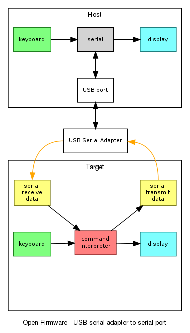
How it works - with a USB serial adapter
When a USB serial adapter is plugged in, and the serial program started, then keyboard input is passed by the program to the USB serial adapter, and thence to the target. Data from the target is received and displayed.
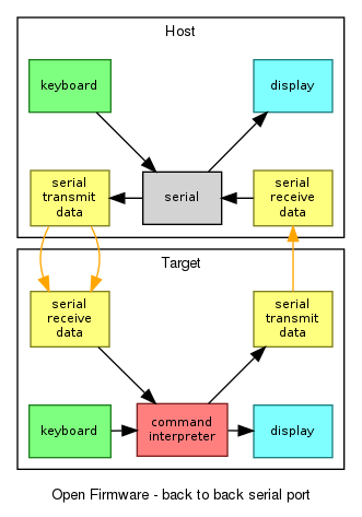
How it works - serial ports connected back to back
This diagram shows when serial ports are connected back to back, with the serial program already started. Keyboard input on either the host or the target eventually reaches the target command interpreter.
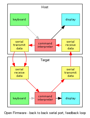
How to fail - doing things in the wrong order
This final diagram shows a pathological data loop. The serial program has not been started, so the Ok prompt from one host is sent as if it is keyboard input into the other host, which sends it back to the first host, and so on.
To avoid this:
- use a USB serial adapter, or
- keep the target power off until the
serialprogram has been started.
References
- terminal.fth
- mailing list post,
- git repository via web, (before it was merged),
- git://dev.laptop.org/users/quozl/olpc-firmware-terminal.git git repository (before it was merged),


