88W8388
The 88W8388 is a wireless controller chip made by Marvell. It is part of the unliberated Libertas chip family. Outside of this page, it is undocumented.
The problem is bug #46 and bug #429 in trac.
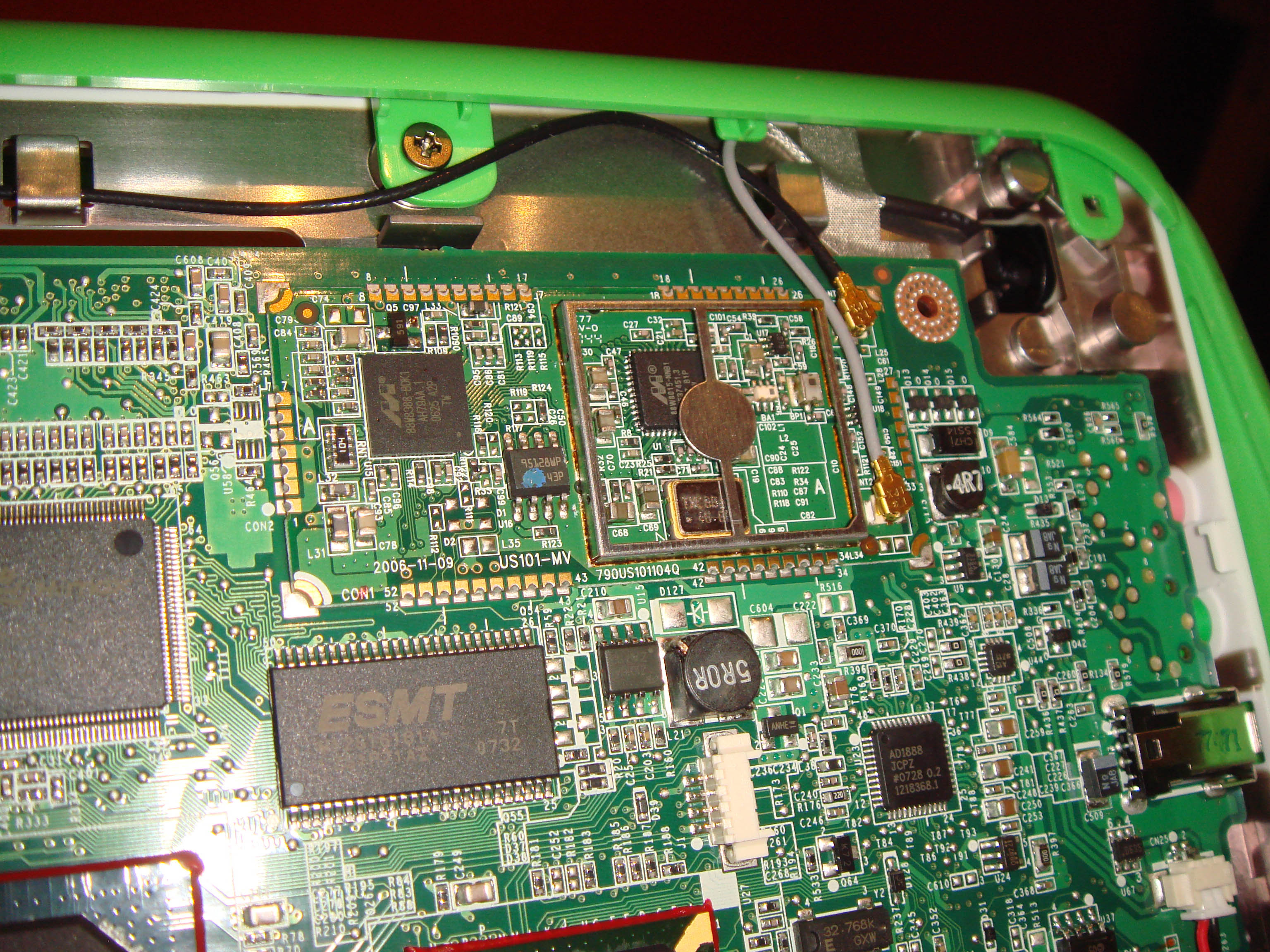
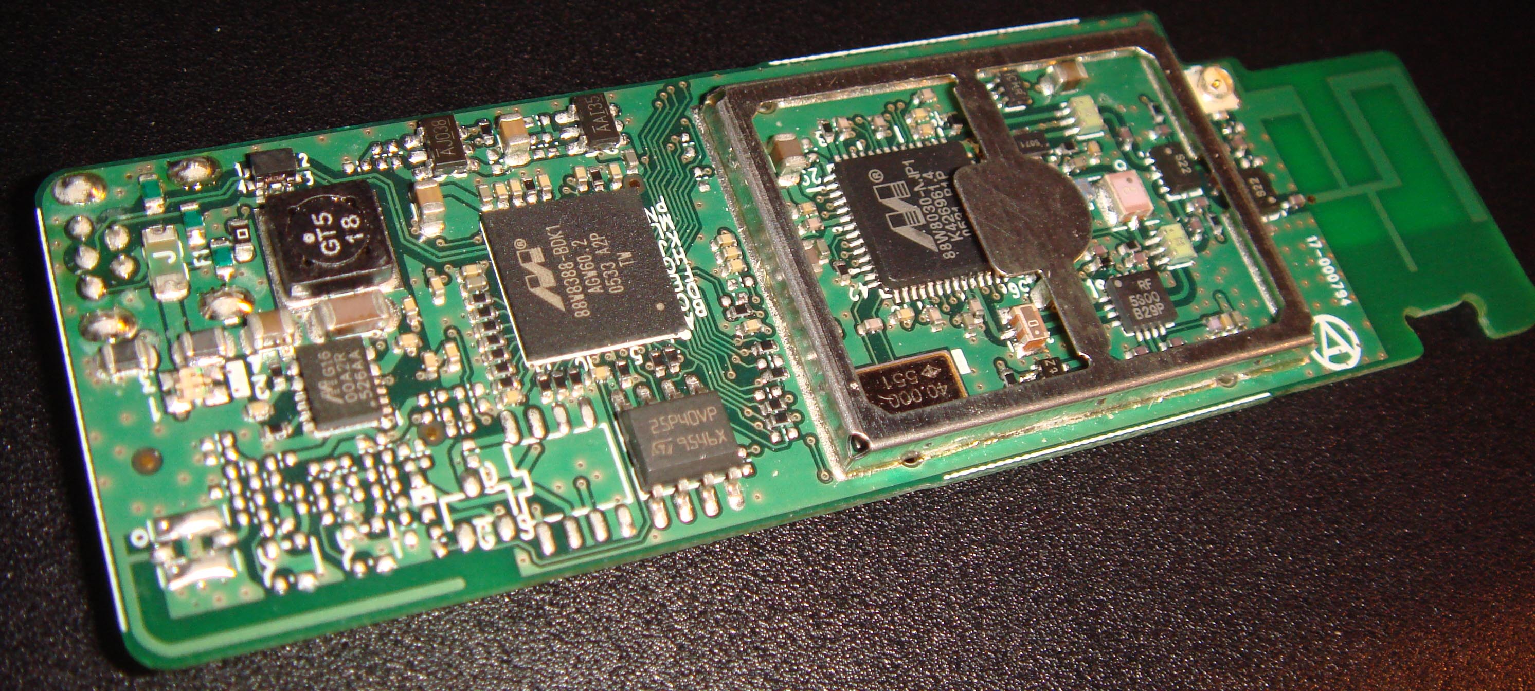
Close-up pictures of the XO's wireless module and the similar Xbox360 wireless device may be of interest. The XO uses an 88W8015 radio chip with a 48 MHz crystal, while the Xbox360 uses an 88W8030 chip with a 40 MHz crystal.
Contents
Critical TODO items
- Find any JTAG, serial port, or audio (supposedly!) connections
- Dump out the ROM
- Get ARM cross-compiler stuff into Fedora, or at least into the OLPC RPM repository. Building these tools on an XO is impractical.
Gross memory map
00000000 0000ffff RAM (code) repeating every 64 KiB
04000000 04001fff stack
80000000 8000ffff IO memory
90000000 9000ffff IO memory
c0000000 c0027fff RAM (code, data, bss, heap) repeating every 256 KiB
fff00000 ffffffff boot1 ROM, 8 repetitions of 128 KiB containing ThreadX
0xffff0000 is where code execution starts. We call this the boot1 code. It contains ThreadX, but does not normally run ThreadX. Normally, boot1 copies boot2 from an SPI EEPROM to 0x00000000 and enters that at address 0.
boot1 is about 10240 bytes. It self-relocates from 0x00000000 to 0xc00xxxxx (near the end), then loads the main firmware. On 88W8385 hardware, boot1 is in a 4096-byte area at 0xc0000000 and the main firmware loads at 0xc0001000.
The main firmware can come from USB or from SPI EEPROM. It loads into both the 0x0000xxxx and 0xc00xxxxx regions, then starts at a specified address which is normally 0x00000000. 88W8388 firmware starts at 0xc0000000 for the high portion, while 88W8385 firmware loads at 0xc0001000 to avoid clobbering boot2.
CPU
This is an little-endian ARM chip. "xscale" appears to be a good match. Mostly it is used to run thumb code, but some regular ARM code is used as well. ARM code can be spotted in hex dumps because most instructions will start (4th byte in little-endian) with the hex digit "e".
According to the free60 project wikis (Mediawiki without pictures, MoinMoin with pictures), there is an ARM946E-S core (as per the ARM Networking brochure) inside the 88W8388.
Note that objdump is completely unsuitable for disassembling this code. You need an interactive disassembler and/or one that traces code flow. Something like objdump will be unaware of the transitions between plain ARM code, thumb code, and data. It is normal for functions to be followed by constants; a good disassembler will match these up with the code instead of stupidly disassembling them.
A free (GPLed) option is to use adiss. Adiss can disassemble firmware blobs where code, thumb and data are intermixed. This isn't automatic like it would be with IDA Pro, but the level of effort is reasonable. Future revisions will make it easy to share notes (section markers, comments, etc.) without violating copyright. See the October 2007 announcement email for a usage example. Get it via subversion, see here.
Main firmware format
Firmware is a stream of packets like this.
le32      0x00000001 if data follows, else 0x00000004
le32      destination address
le32      data length including final CRC, normally 0x200 bytes
be32      header CRC (1st 12 bytes and 4 zero bytes)
char[508] may be smaller for the last block
be32      data CRC (the 508 bytes and 4 zero bytes)
Data length goes short at the end of a segment. After the very last block of the whole file, there is one special header. It has code 0x00000004, the entry point address (normally zero), length zero, a header CRC, no data, and no data CRC.
Use bin2elf.c and elf2bin.c to convert firmware files to/from ELF.. Use extract.c to extract firmware files from driver files.
CRC
polynomial 0x04c11db7 (common CRC32)
initial remainder 0
no reflections
no inversion at the end
stored in big-endian format!
on creation, include 4 trailing zero bytes
nice property: the CRC of the data with following CRC will be zero
Boot firmware format
It's just 10240 bytes of byte-swapped code. This code, known as Boot2, is flashed into the Marvell chipset. It implements the USB interface required for loading the main firmware.
Gross EEPROM map
0000 027f   config data of some sort, 640 bytes
0280 033f   config data of some sort, 192 bytes (all 1 bits on older hardware)
0340 0fff   all 1 bits
1000 37ff   the Boot2 code, 10240 bytes
3800 3fff   all 1 bits
Use ethtool to read it out in 16-byte chunks. You can grab the whole thing in about 18 seconds.
for i in 0 1 2 3 ; do
  for j in 0 1 2 3 4 5 6 7 8 9 a b c d e f ; do
    for k in 0 1 2 3 4 5 6 7 8 9 a b c d e f ; do
      ethtool -e msh0 offset $((0x$i$j$k*16)) length 16
    done
  done
done
Munge with normal tools (sed,awk,perl,colrm,xxd,grep) as needed to produce a binary file.
IO memory
0x80002018 contains a hardware type code. Shift right by 16 bits then mask with 0x1f to get it. For values of 7 or 18, mmio1 is 0x90000000 and mmio2 is 0x90000800. For other values, mmio1 is 0x8000c000 and mmio2 is 0x8000c100. The content of 0x80002018 on an Xbox360 is 0x004269aa, leading to a value of 7. The XO has a value of 7 (likely) or 18. Thus mmio1 is at 0x90000000 and mmio2 is at 0x9000800.
mmio1+0x200 is GPIO output enable X, 2 bits per GPIO. When a field is set to 1, output works. Values of 0,2,3 (typically 0) choose stuff like the 16550 UART, transmit/receive blinks, etc. Since this MMIO area is only 16 bits wide, this register requires two addresses. The low 8 GPIO lines are here, and the high 8 are at mmio1+0x204.
mmio1+0x204 is GPIO output enable X, part 2. See mmio1+0x200 for details.
mmio1+0x208 is GPIO output enable Y, or GPIO input enable. It is 1 bit per GPIO line. Setting a bit causes the GPIO to be used for input. Clearing a bit causes the GPIO to be usedfor output.
mmio1+0x20c is GPIO output. The two low bits, GPIO0 and GPIO1, are normally attached to LEDs. On the Xbox360 these are inverted logic, with bit 0 being !red and bit 1 being !green.
mmio1+0x210 is GPIO input.
An input GPIO10 of 1 tells the XO's boot2 code to boot from eeprom. (read mmio1+0x210, then mask with 0x400) It is likely that this distinguishes a laptop from an Active Antenna.
90000000 w8
90000004 w8
90000200 r32 w16 w32
90000204 r32 w16 w32
90000208 r32 w16 w32
9000020c r32 w16 w32
90000214 r32 w32
90000218 ?
90000220 r32 w32
90000228 r32 w16
9000022c r32 w16
90000230 r32 w16
90000234 r32 w16
90000238 r32 w16
9000023c r32 w16
90000240 r32 w16
90000244 r32 w16
9000024c r32 w16
90000254 r32 w32
90000800 r16
90000804 r32 w32 r8 w8
90000806 r8
90000808 r32 r16 w16
9000080c r8
9000081c r8             poll until bits among 0xc3 are set
90000824 r32 w32 r8 w8
90000828 w32 w8
9000b010 w32
9000b014 w32
9000b018 w32
9000b024 w32
9000b028 w32
9000b02c w32
9000b030 w32
9000b034 w32
9000b038 w32
9000b03c w32
9000b040 w32
9000b100 r32 w32
9000b118 w32
9000b11c w32
9000b120 w32
9000b124 w32
9000b128 r32
9000b12c r32
9000b130 r32
9000b134 r32   a low bit we can poll for a change
Standard interface
The proprietary firmware implements an interface which the Linux driver uses. There is also a list of corrections for that document.
DMA
The firmware's view of DMA involves something like this:
struct dmainfo {
    unsigned bytes;
    char *src;
    char *dst;
    struct dmainfo *next; // NULL for last block
}