Charging-XOs
Charging XO Battery by SMPS
Introduction
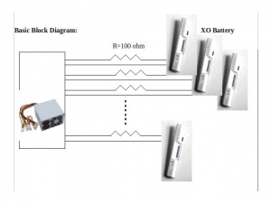
Multiple charging to XO at schools at a same time is a challenge because of power plug constraints. This can be done by using SMPS (Switch Mode Power Supply). This article will help to understand how to charge multiple XO battery by SMPS
Components Required
TO parallel charge 10 external XO Batteries
SMPS- 1 No.
4 Pin peripheral connector male with wire – 1No.
Fasten Lug Terminal 6.5mm Male with Crimped wire. – 20 Nos.
100 ohm 2W resistors – 10 No.
Digital Multimeter - 1 No.
Insulator tape Roll
Solder wire 70:30 Joint
Solder Iron 25W - 1 No.
Basic Idea of the above components
SMPS: Its stands for Switch Mode Power Supply, its just a switcher which a switching regulator in order to provide the required output voltage. Its converts AC (Alternate Current to DC Direct Current).
4 Pin peripheral connector male with wire : To connect with SMPS.
Fasten Lug Terminal: It is male connector to XO Battery.
100 ohm 2W resistors: This is used to get the required output voltage. Power delivered by SMPS is more than required, So to provide the required input to XO battery, Unrequited Voltage is dropped on the resistor.
Digital Multimeter: It’s a electronic device which is used for finding voltage, current, resistance of any circuit. Here it is used to find out whether battery is charged or not .When the voltage across the XO battery reached to 7.5 V means battery is fully charged.
Insulator tape Roll, Solder wire 70:30 Joint, Solder Iron 25W: Are used for cabling purpose.
