Cow Power
Contents
Motivation
We wanted to develop alternative power solutions at the OLPC pilot project site at Khairat Village. Our approach was to not look from a motor/dynamo etc. point of view. Our approach was to develop power solutions around locally available mechanisms. At the village (pilot site near Mumbai) we explored the ideas of using solar power (in Mumbai sunlight is not consistently strong) , running water (we couldn't find any local water bodies nearby), wind power (no wind in the that area), mounting small dynamos on bicycles (we found out that in that area bicycles aren't that common at all, esp in that village) .But the village had an abundance of cattle - that were being used in the fields. So we decided to design something around that.
Having said that, the solution is of course not a one-for-all solution, but is an example of how locally available mechanisms can be leveraged to charge the laptops. The mechanical and electrical design would be re-usable in a way that other driving mechanisms at other places could be used to drive a dynamo/alternator by following a similar design approach.
We considered using a small motorcycle/moped engine , but that would lead to recurring costs of petrol/diesel for the villagers, hence we decided against it. Minimizing costs, is an important factor for easy replicability.
Current Mechanical Design
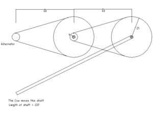
We are using a system of belts and pulleys to get a high rpm at the alternator. This alternator has been taken from the ones used in trucks. Calculations for this prototype are as follows -
linear velocity of cow = 0.7m/sec
w(in) = 2.8 rpm                                (Angular velocity of the shaft rotated by the cow)
lenght of shaft required = 2.37m               (The shaft that the cow rotates)
reduction ratio (big wheel R=21cm, small pulley r=4cm) y=5 X 5 = 25
w(alternator) = w(in) X y = 70rpm
70rpm give us about 1.5A current output which is enough to charge 2 XOs.
Proposed Mechanical Design
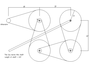
To get a higher current output from the alternator and hence a higher rpm at the alternator, we need to increase the ratio by which our rpm gets converted. This is a proposed design.
The calculations for the proposed design would hence change to -
reduction ratio = 25 X 25 = 625
w(alternator) = 1700 rpm
This rpm would give us about 10A which is enough to charge 10 XOs simultaneously.
An important factor to consider here would the force/tension in the belt at the slowest rpm. Say our alternator is giving out 12V and 10A output. This amounts to 120W of output power. Assuming losses in the system and a reasonable efficiency of the alternator, lets say that the power input of the system is 200W. That is, the cow is delivering 200W of input power into the system.
P = 200W
w = 2.8rpm
r = .21m
using P = Tw and T = Fr we calculate F as
F = approx 3500N
Hence the tension in the first belt is about 3500N
Pictures of current prototype
How you can help
Electrical Design
Requirements
- Regulate current. The XOs at Khairat school have LiFePO4 type batteries. Let us chose a 1A charging current so that with the given capacity of the dynamo, we can charge about 15 XOs simultaneously. See Battery Charging for more details about all kinds of batteries that are used in the XO
- Regulate voltage. The XO power supply accepts voltage from 9V - 18V . The charging circuit switches on at 9.85V. Let us chose to fix the voltage that we give the XO at 12V
Design approach
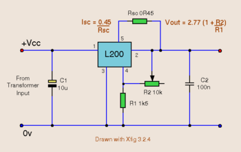
- Using L200 as the central component - it is cheap, easily available and most of all robust
- Referring to this sample circuit and deriving parameters from this design guide
- To avoid effects of shorting or reversing of supply from dynamo to the L200 circuit a simple full wave bridge rectifier using 1N5408 diodes has been used. Also, a 100uF 35V decoupling capacitor is being used after the rectifier.

Deriving circuit parameters
- For values of R2 and R1, I referred to table in right column of Page 4 of design guide. Selecting Vo=12V +-4% I get R1= 1K ohm +-1% and R2=3.3K +-1%
- Since Isc = 0.45/Rsc (according to sample circuit design), I chose Rsc=0.47 ohm 1/2 watt
- Current in R2, Ir2=(Vo-Vref)/R2 where Vref = 2.77V. Hence power dissipation in R2, Pr2 = 25.8 mW
- Current in R1, Ir1=Vref/R1 = 2.77mA . Hence power dissipation in R1, Pr1 = 7.7 mW
- Hence R1 and R2 can be chosen to be 0.25W type

