Measure/Blog
Contents
(be sure to include as many pictures as you can)
Some of my ideas, thoughts, back-of-an-envelope sketches and musings regarding hardware interfaces to Measure:

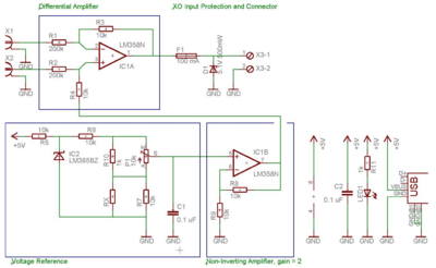
I've added a fuse and 5.1V Zener diode on the XO input, as you can see - this should, hopefully, be suitable for making these types of electronic interfaces for Measure robust and "noobie-proof".
- This is all my half-baked, untested, back-of-an-envelope stuff - no promises it works! Peer review, comments, feedback, or criticisms are all welcome.*
I don't claim all these ideas as unique or new - but I'm trying to take existing project ideas from the projects page and flesh them out a little more.
- I don't have access to an XO-1 machine - if any developers who do might like to test my ideas, as they mature, I'd love to hear the results!*
Project ideas
Measuring daily changes in solar irradiance:
Using a suitable interface, such as the above, or even a simple voltage divider, to measure the DC voltage from a photovoltaic module, and log how it changes over a period of a day - I'm sure we could even use the OLPC photovoltaic charging module for this - it has a 12V DC output - just make sure your amplifier/buffer interface will be suitable for the 12V input, and will scale it down to 0-3V, and plug it in!
Optical barrier alarm:
Turn on the voltage bias, and connect a LDR. Say our LDR has 500k dark resistance and max 2800 ohms in light. (That was measured from a mystery one in my junk box.) Given 785 mV bias with 790 ohms effective impedence, we have then, 784 mV dark input voltage, and 612 mV light input voltage - quite detectable discrete levels.
1 mW 660nm red laser diode modules are cheap and easily accessible for experimenters - but remember, if working with children or young people, teaching prudent laser safety is a good idea, even at this power level.
Temperature acquisition:
Using the simple LM335 probe, described in detail at Measure, a simple classroom demonstration of Newton's Law of Cooling can be realised, using the computer as a datalogger.
Biomedical instrumentation / Demonstration-grade Electrocardiography:
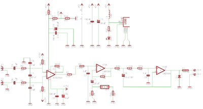
This isn't intended to be a fully fledged, powerful, diagnostically suitable or useful ECG platform in the same way that TeleHealth is aimed at realising - but it should work, and it might even work well enough with the XO's integrated ADC to work as a proof of concept, or a demonstration.
It's a simpler, smaller, cheaper, non-diagnostic ECG, that might be valuable as a teaching or demonstration tool. It will certainly work, and show an ECG signal. At least, it should.
This only has two electrodes - and needs to be combined with an ADC - probably the XO's inbuilt ADC - the voltage levels will always be within 0-5 V.
As in the above schematic, a 5.1V Zener diode can be included on the input line to the XO to clamp it - along with a fuse to limit current into the XO at 100 mA; "just in case".
Also, as in the schematic shown above, power is also derived from the USB port's 5V rail.

