OLPC India/Khairat Technical
(draft/template)
Contents
- 1 Comments
- 2 Deployment of Laptops in general - reaction, expectations and feelings
- 3 School server - default setup and road ahead
- 4 School server - power solutions
- 5 Providing internet in the remote village
- 6 Localization, Keyboard and Fonts
- 7 The Sugar experience
- 8 Overview of observed Bugs
- 9 Scale and replicability of pilots and deployments
- 10 Alternative power
- 11 Mechanical design
- 12 Electrical design
- 13 =Acknowledgments
- 14 Internet connectivity at pilot site
- 15 Wireless tests
- 16 Sharing Experience
- 17 Working with content creation groups
- 18 Comments
Comments
- All photos are by Carla unless otherwise stated.
- The following are my views and may not necessarily reflect that of OLPC. For official clarifications on any of the technical aspects, please contact people at OLPC directly.
Deployment of Laptops in general - reaction, expectations and feelings
School server - default setup and road ahead
School server - power solutions
Providing internet in the remote village
Localization, Keyboard and Fonts
The Sugar experience
Overview of observed Bugs
Power adapters and their alignment
Touchpad
The journal
Some XOs on the 613 images had their Journal gone. Image 616 fixed that bug. Once the teacher lost his files. As a result an automatic backup script was written by Amit in the site. --Carla 16:56, 30 October 2007 (EDT)
Scale and replicability of pilots and deployments
Alternative power
The power supply in town is not very reliable, so many days we didn't have power, or had it intermittently. The children tried to bring their XOs charged, but still some needed to charge them at school. --Carla 16:56, 30 October 2007 (EDT)
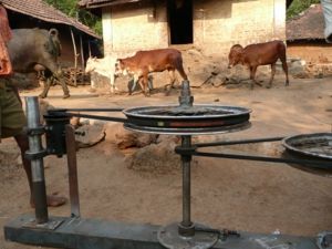
Cow Power Design Notes
Mechanical design
Electrical design
Requirements
- Regulate current. The XOs at Khairat school have LiFePO4 type batteries. Let us chose a 1A charging current so that with the given capacity of the dynamo, we can charge about 15 XOs simultaneously. See Battery_Charging for more details about all kinds of batteries that are used in the XO
- Regulate voltage. The XO power supply accepts voltage from 9V - 18V . The charging circuit switches on at 9.85V. Let us chose to fix the voltage that we give the XO at 12V
Design approach
- Using L200 as the central component - it is cheap, easily available and most of all robust
- Referring to this [ http://www.zen22142.zen.co.uk/Circuits/Power/l200.html sample circuit ] and deriving parameters from this design guide
- To avoid effects of shorting or reversing of supply from dynamo to the L200 circuit a simple full wave bridge rectifier using 1N5408 diodes has been used. Also, a 100uF 35V decoupling capacitor is being used after the rectifier.
Deriving circuit parameters
- For values of R2 and R1, I referred to table in right column of Page 4 of design guide. Selecting Vo=12V +-4% I get R1= 1K ohm +-1% and R2=3.3K +-1%
- Since Isc = 0.45/Rsc (according to sample circuit design), I chose Rsc=0.47 ohm 1/2 watt
- Current in R2, Ir2=(Vo-Vref)/R2 where Vref = 2.77V. Hence power dissipation in R2, Pr2 = 25.8 mW
- Current in R1, Ir1=Vref/R1 = 2.77mA . Hence power dissipation in R1, Pr1 = 7.7 mW
- Hence R1 and R2 can be chosen to be 0.25W type
=Acknowledgments
Thanks to Richard Smith for help in the electrical design.
--Arjs 11:18, 16 November 2007 (EST)
Internet connectivity at pilot site
Wireless tests
Village topology
Conditions
Range and results
Sharing Experience
In the classroom
Amit and I, together with the teacher and the children, did some testing on the Mesh by sharing activities. Children were working on the laptops and did different kinds of sharing to work with their classmates. The Sharing Activities wasn't that intuitive, we weren't really successful with it. Nevertheless, the children who shared activities were super-happy. --Carla 16:56, 30 October 2007 (EDT)
Working with content creation groups
Comments
I was very involved with the technical side with Amit, until Manu and Arjun arrived. I still was in the loop but more involved with the educational side. So, I'll focus on the aspects that had an impact on the educational side Khairat Chronicle. We worked with the developers daily to tackle these issues. --Carla 16:56, 30 October 2007 (EDT)


