SPI FLASH Recovery/XO-1
Contents
SPI FLASH Recovery
If the SPI boot FLASH somehow gets bad data in it, so the firmware won't run, you can reload it with a special serial cable.
The cable connects to CN24 (Recovery Connector) on the Btest boards (CN20 on Atest). 
In addition to connecting the special cable to the Recovery Connector, during recovery you also must install jumpers in both positions of the Recovery Mode Jumper Block. It doesn't matter whether you install the jumpers horizontally or vertically; either orientation will work. If you don't have any jumpers the right size, you can wedge a metal object into the block, connecting all the pins together. A screw about 0.1" in diameter works well. Or wrap a piece of wire around the 4 posts.
Atest jumper
For the Atest board, there is no jumper block. You have to solder a wire across a couple of pads. They are just to the left of the ene chip, near the middle of the left row of pins on that part; see media:AtestRecoveryJumper.jpg.
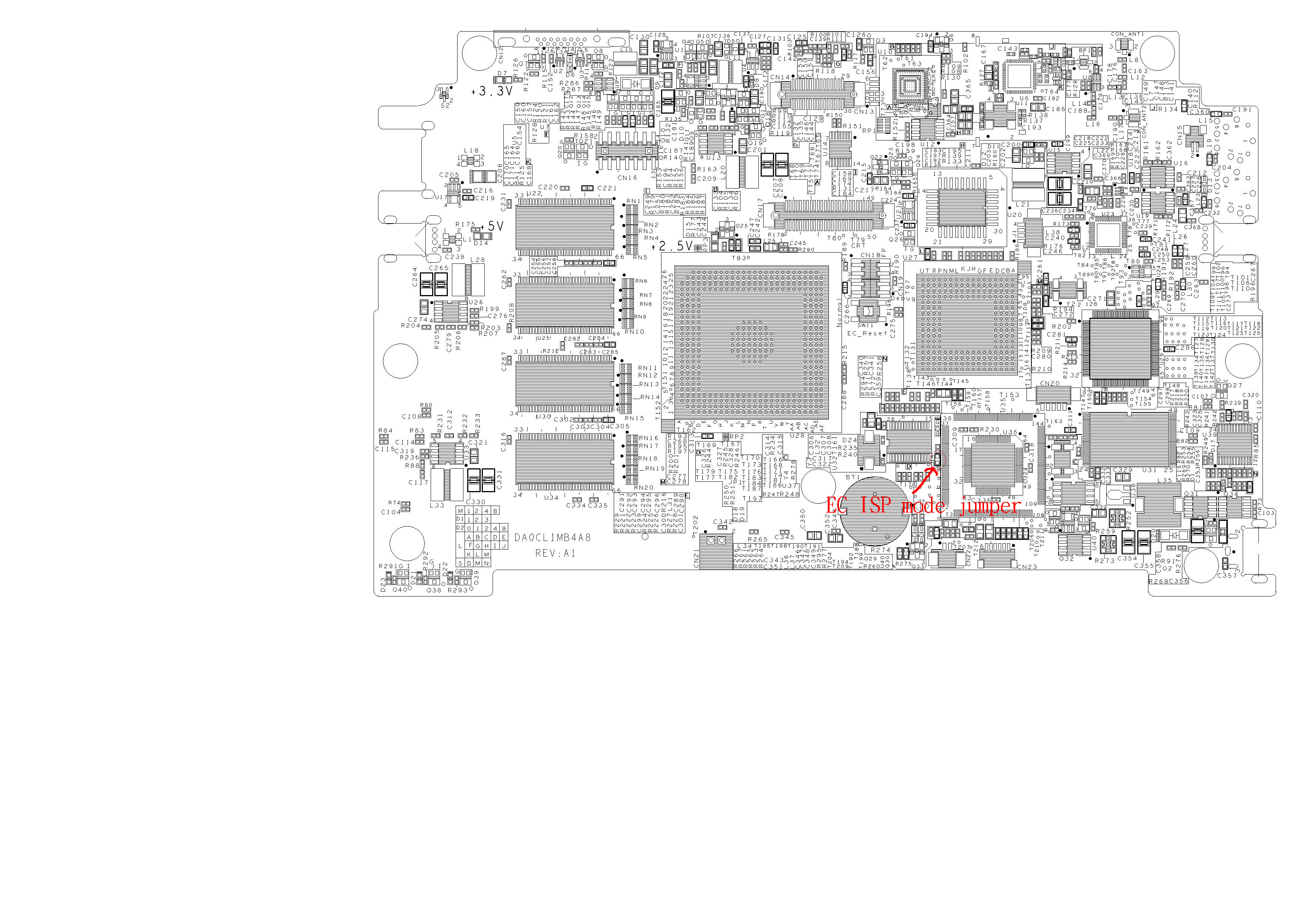
Connecting the Linux Host to the OLPC Board
Connect a "null modem" serial cable from your Linux host machine to the DB9 connector on the special recovery cable. Typically, the null modem cable will have DB9 female connectors on both ends. If possible, connect it to the host COM port that is associated with /dev/ttyS0 - typically COM1. If your host system doesn't have a built in COM port, you'll need to use a USB-to-serial adapter and figure out the associated device name.
Getting the Software
http://firmworks.com/linux/spirecovery.tgz contains a Linux application to perform the recovery procedure. The archive contains two files: forth and spiflash.dic . The two files work together. forth is a Linux executable file that provides I/O interfaces that let the Forth programming language work under Linux. spiflash.dic is a Forth language workspace (AKA "dictionary") that includes procedures for performing the serial line recovery protocol.
Get that archive and unpack it into a working directory that contains the boot FLASH image file that you want to install in the OLPC board (that file is typically named linuxbios.rom).
Make sure that the "forth" file has execute permissions.
chmod a+x forth
Running the Program
Start the program with
./forth spiflash.dic
It will display a page of instructions describing the various commands, then issue an "ok " prompt.
Look at the software version number on the first line of the instructions that are displayed. If it says version 1.0, you need to download a new copy of the software from the web site. Version 1.0 works, but is more complicated to use. The instructions below are for version 2.0.
Here is an example of a typical command sequence for reflashing the entire SPI FLASH, including the EC code and the BIOS.
First make sure that all the connectors are hooked up and the jumpers installed.
The default serial port is /dev/ttyS0. Do the next line, substituting your port name, only if you are using a different port:
ok line /dev/ttyS4
Connect power to the OLPC board, then:
 ok flash linuxbios-Q2A11.rom

 SPI FLASH is type 13 - Spansion, Winbond or ST
 Erasing
 f0000
 Writing
 ff000
 Type verify if you want to verify the data just written.
 Verification will take about 17 minutes...
The default image filename is olpc.rom . That name will be used if you omit the filename on the "flash" command line.
If you don't see the "SPI FLASH is ..." message, i.e. if it fails or hangs, it means that the host system can't talk to the OLPC board. Check the connectors, jumpers, etc, and make sure that you are on the right serial port on the host.
If you have re-issue the "flash" command, like for example you control-C out of the program and restart it, you'll need to power-cycle the OLPC board. The OLPC board will only accept incoming connect attempts after a power-up. If you have already connected to it once, you can't reconnect without power-cycling.
The flashing process should take between 1 and 5 minutes, depending on how much unused (set to 0xff) space there is in the image.
Note that, unlike some earlier versions of our FLASHing software, this program always updates the entire FLASH in one step. There is no separate procedure for updating the EC code versus the BIOS code. The reason is because there is no advantage to preserving the EC code on the new boards that do not have have a separate PLCC socket. Lacking a PLCC socket, if either part of the FLASH is bad, the only alternative is to update the FLASH via the serial recovery procedure. The simplified procedure guarantees that consistent EC and BIOS code will be loaded simulataneously.
Verification
Verifying is quite a bit slower than programming, due to the characteristics of the serial protocol coupled with Linux scheduling issues. The net result is that programming goes at about 5K bytes per second (for most parts), while reading (necessary for verification) goes at 1K bytes per second.
So programming all the bytes of a 1 MiB SPI FLASH takes about 3.5 minutes, while reading or verifying them takes 17 minutes. Ouch!
Since verifying is so slow, you might consider not doing it. Most of the time the writing process will work just fine, and you can boot the system and let the running firmware do the verification at memory access speed.
Reading the SPI FLASH
To read the contents of the SPI FLASH and save it to a file:
ok read-flash myfile.rom
This will read the entire 1 MiB FLASH, which will take about 17 minutes.
Exiting
To exit, type
ok bye
(or ^C).
Powering up the btest Board
- Turn off the power to the btest board
- Remove the recovery jumpers
- Turn the power back on
- (For recent versions of the EC code) Press the "Power Button" (SW2) which is on the bottom of the board underneath the SD socket. The nearby green LED should come on.
- (If your board is one of the early preB ones that doesn't have the fix for the CaFe configuration delay) Briefly short JP2, which is a pair of triangular pads below the 5536 chip (where "below" is relative to the orientation where the power connector is at the lower right corner).
Having done all that, LinuxBIOS should start.
Serial Protocol
This section is just for the curious (there are lots of curious people on the OLPC project). You don't need to know anything in this section to accomplish the recovery task.
The way the serial protocol works is by letting you read and write, via the serial line, the EC registers than control the SPI FLASH programming. Writing to an EC register requires sending two serial line bytes - a register number and a data byte. Reading an EC register also requires two serial bytes - sending the register number and receiving the data.
For most of the SPI FLASH chip types (Spansion, Winbond, ST), writing is reasonably efficient. After a few bytes of setup, you can transit a stream of 256 consecutive data bytes with two serial bytes per FLASH data byte - a fixed register number followed by the data byte. The SST part's write procedure is a bit more complicated. (The astute reader will no doubt wonder why the EC designers did not improve the protocol so that only one serial byte per FLASH byte is required. Your erstwhile author wonders that too.)
At 115200 baud, you can transfer roughly 10K serial bytes per second, so you can write about 5K FLASH bytes per second (there is also some time for the FLASH part to actually do the writes, but that is fast compared to the serial line).
Reading is not so efficient. The way the EC works, in order to perform an SPI read cycle, you must first issue a "dummy write" cycle then read a register to get the data. The purpose of the dummy write is to generate 8 clock cycles on the SPI bus, during which the FLASH chip sends the data back. The net result is that reading a byte with the serial protocol transfer 4 serial bytes - two sends for the dummy write, and a send and receive for the data read. So reading inherently takes twice as long as writing. It would work out to 2.5 Kbytes per second, and indeed I can achieve that throughput with a host program running "standalone" without an operating system.
But in practice, it's worse than that under Linux, at least on the Linux installation that I have tested it on. For some reason, Linux throttles the serial "write, write, write, read" sequence so I get exactly one iteration of that sequence per millisecond. That works out to reading 1K bytes per second. I've tried many variations of raw serial I/O with different settings for VMIN and VTIME, both blocking and non-blocking, to no avail. Note that it's not practical to read more than one byte with a single read() call, because the "write, write, write" sequence for the next byte can't start until the "read" for the previous byte has finished.
Note: it is possible to run most PC serial ports at faster than 115200 baud, but it requires special driver code that is chipset-dependent. Using that feature would have greatly complicated these procedures.