XO 1.5 C5
XO-1.5 Laptop model C5.
Contents
Description
The C5 was one of the XO-1.5 (CL1B) versions in production.
Identification
Externally identical to XO-1 with capacitive (single) touchpad, except for three raised dots on each side of the hinge cover:

Internally:
- The WLAN is on a removable daughtercard
- Some XO-1.5 have all eight memory chips populated (1 GiB), and some have only four memory chips populated (512 MiB).
Rev M
- Motherboard revision M - using Intersil ISL6218 Vcore and ISL9519 battery charger circuits (on the motherboard this is marked as DACL1MB16A0 Rev. A)
- Open Firmware cpu-model OLPC DA (models are in hex. 10 = 0xA).
Rev L
- Motherboard revision L - using Intersil ISL6218 Vcore and ISL9519 battery charger circuits.
- Open Firmware cpu-model OLPC D7 and D8 (with Open Firmware modifications which greatly increase the likelihood of C3/C4 working).
Annotated Motherboard

Software Support
Firmware
XO-1.5 C5 laptops should use Q3Cxx firmware releases. These will also work on earlier XO-1.5 laptops (C2/C3) but will not work on an XO-1.
If you upgrade the Linux distribution on a laptop, it contains a recent version of firmware which will be automatically installed on the next reboot when both DC power and a battery are present.
Obtaining Firmware
C5 motherboards require an Open Firmware release equal to or later than Q3B01. We currently suggest using the latest.
Check the XO 1.5 EC dev changelog for information about the latest EC firmware, integrated into the above Open Firmware releases).
Installing Firmware
See upgrading firmware.
Linux
See release notes.
Hardware Limitations

The currently known hardware limitations are:
Serial Port
The processor serial port situation on XO-1.5 is not optimal, as it shares pins with the camera interface. There is a connector (J4) located on the upper left hand side of the motherboard for +3.3V RS-232 connection (see the pinout and the connector/jumper locations), but its use must be enabled using a jumper or properly wired serial adapter, present at boot.
The new serial adapters for XO-1.5 laptops automatically enable the serial port when connected at boot. They do this by tying pin 1 to GND (pin 4) through a 1K resistor.
Serial adapters used with XO-1 will work with XO-1.5, but you will have to manually enable the serial port. To do this, you will have to either short pins 1 and 3 on the SERIAL ENABLE jumper (JP1) or short PR148. JP1 is located right behind the processor serial port. Pins 1 and 3 are the two pins closest to the memory chips. PR148 is a large power resistor located near the processor serial port (see the XO-1.5 connector locations). You can use a pencil, rubbed repeatedly across PR148, to enable the serial port. An eraser can be used to disable the port.

There is no need to disconnect the camera in order to use the serial port. Any use of the camera while the serial port is enabled will generate constant spurious serial data. To fix this, the Linux camera driver will not load if the serial port is enabled --- thus disabling power to the camera.
If the SERIAL_ENABLE jumper is set, the camera in-use LED will remain lit. This will not be fixed (Trac ticket #9385).
Initial Powerup
If the power button (or any other button around the screen) is pressed when power is first applied to a laptop, it will fail to boot (or show any signs of life). This is not an issue if a battery with some charge is in the laptop. This only occurs when either the main battery is completely dead or missing, and a DC power source is plugged in.
If one of these buttons is held down as the EC comes out of reset (when it flashes the battery and power LEDs), the EC is placed into a test mode. ALL XO models (1 and 1.5, prototype and production) have this problem, but you are more likely to encounter it in an early production XO-1.5, due to the roughly 1s delay between applying power and the EC resetting.
The 1s delay was due to a last minute change to improve solar panel performance. Fixing it requires a MB change, which will be rolled in starting around September, 2010.
The actual problem (pressing the power button, or any other button around the screen, will prevent the EC from booting properly) will not be fixed in XO-1 or XO-1.5.
Documentation
Supporting documentation for these boards are (in PDF):
- Motherboard Schematics
- Pinouts
- Connector Locations
- GPIO Mappings
- EC Pinout
- EC Power On Sequence
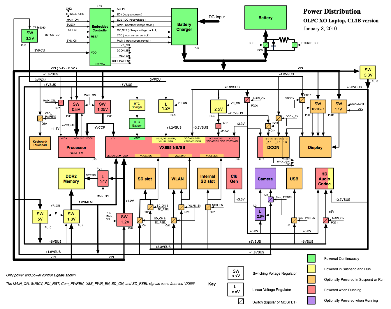
- Power Distribution Diagram (PDF)
- Motherboard Photos