Disassembly/Archive
Cautions
Eye damage. There is a risk of damage to your eyes due to small pieces of metal or plastic releasing due to force stored during manufacturing or structural stress. Solution: protect your eyes.
Static discharge. There is a risk of damage to the system if you touch electronic components. You will not necessarily feel the discharge for it to do damage. The damage is not necessarily immediate, the system can fail some months later. The damage can be cumulative. Solution: ground yourself before working on your laptop.
Remove the main battery and the power cable before starting disassembly There is low risk of electric shock, since low voltages are used inside the system. However, there is a risk of accidental shorting with tools or screws. There will remain a clock battery on the main circuit board, powering a small number of circuits.
Be careful with the motherboard Avoid dropping metal objects on the motherboard. The components used are small enough that dropping a screwdriver on the board may knock off vital components.
Tools
- philips head #1 screwdriver,
If you have them:
- anti-static mat or anti-static wrist strap,
However, if you do not, touching a grounded portion of the laptop case (e.g. the screen casing or the heatsink on the motherboard) prior to handling the exposed electronics is usually sufficent to prevent any static damage. Things like extremely low humidity, or wearing synthetic fabrics may increase the risk of static discharge.
Procedure
The official disassembly section of the OLPC manual can be found at Manual/Insides. Many people find this version much easier to follow.
Remove Power
- remove the power cable,
- remove any USB or audio cables,
- remove the main battery,
Front
- set the brick (lid) at 90 degrees to the base, as if you are moving to e-book mode,
- close the antennae,
- rotate the brick 90 degrees to the left,
- examine the brick base,
- unscrew the two screws that are revealed (philips head #0),
- rotate the brick 180 degrees to the right,
- remove the other two screws revealed.
- open the antennae,
- apply upward finger force to the short green bumpers, and they should slide up and be removed,
- remove the plastic face plate over the LCD,
Back
- remove four (4) screws holding down LCD panel,
- carefully lift the bottom end of the LCD, leaving the top in place, to gain access to the two (2) screws underneath that hold on the back,
- remove the four (4) screws that hold on the back, (two covered by the LCD, two not covered by the LCD),
- if you are only changing the antennae, you can temporarily screw down the LCD with a couple of screws,
- slide the back panel down a bit before it will pop off,
Top
- the green top piece is held on by four (4) screws (or 2, depending on the model?) that are behind the back panel,
Antennae
- pull the antenna connector off the radio module, (in the absence of a proper extraction tool, a pair of pliers held lightly will do, but take care not to crush the connector),
- remove the two (2) screws holding down the antenna hinge structure, (on a B1 this structure is black plastic),
- remove the antenna and hinge structure from the system, threading the cable out through the access hole,
- remove the hinge structure and affix it to the replacement antenna, with identical orientation,
- thread the cable in through the access hole,
- screw down the hinge structure,
- push the antenna connector onto the radio module socket, (something with a flat end is useful here, the idea is to get the insertion force vertical, and leave no accidental sideways force ... it is very easy for the connector to roll sideways).
Note: before re-assembly, the antennae may seem to deviate from alignment when in the stowed position. This will change once the bumpers are put back on. The tops of the antennae meet the green bumpers in a way that brings them closer to the case.
Keyboard and Touchpad
Note that you don't have to take apart any of the top (lid) half to get at the keyboard and touchpad. I'll assume in these instructions that the lid is whole.
Hinge cover
(You don't have to do this bit, but removing the hinge cover makes it a little easier to get the next part off.)
- Open the lid and swivel it 90 degrees, like you're starting to put it in ebook mode
- Remove the 2 screws on the top of the little piece between the hinge and the pivot
(Tip: Turn the screen 180 degrees between removing screws to help you avoid banging the LCD with the screwdriver.)
- Swivel the lid back and open it all the way
- Pull out the half of the hinge cover in the front
- Close the lid
- Remove the other half of the hinge cover
Top of handle
- Close the lid and flip the XO
- Remove the 5 screws in the battery compartment
- Flip it back over
- Lift the front of the white panel behind the hinge (Pick the XO up and push up on the sloping bit in the middle of the battery compartment if you can't get it started.)
- Remove the panel (The back has tabs that slide into the green part of the handle.)
- Remove the 4 screws that go into green plastic (The other 6 screws seem to be extras, in case you lose one.)
- Slide the top green bar up and off
Hinge
- Note the two cables coming out of the lid. One goes into a connector. This goes to the battery compartment. Unplug it(You might take a small flat head screw driver, place it's corner in each groove, facing away from the arrows of each of the two plastic prongs which hold it in place. Then push the screw driver forward, wiggling it slightly, until each prong is free.)
- The other one goes to the keyboard and touchpad. (Its plug it further in, we'll get to it later.)
- Remove the 4 screws that hold the base of the hinge down.
Tip 1: You can do this either with the lid open and swiveled, or closed. For opened, it helps to have a second person to steady it as you remove the last screw. For closed, I suggest opening it just a few degrees first or it'll be hard to get back together.
Tip 2: Be careful! That cable is the only thing left holding the 2 halves together now.
Bottom
- Flip it
- Pop the top of the bottom panel out from where the green rails on the sides curve inward
- Slide the panel up and it should pop out (You might have to wiggle it it bit.)
- Lift the cloth-covered cable from the metal plate (It's stuck down with a strip of gummy restick glue.)
- Unplug the cable from the socket on the circuit board
- Remove 4 screws and slide off the green bar at the bottom
- Remove 2 screws from the rail on each side
- Flip it keyboard-side up
- The rails snap off, with 2 snaps along the edge (See picture below - one snap is around the top of the first row of keys, and the other is near the bottom of the row with Ctrl)
Tip: It helps to slide a plastic wedge down between the rail and white plastic. I used the very rounded nail-clipper handle in the picture. The green bar at the bottom you just removed works as well - use the tabs that stick out (the ones with holes for the screws to go into them) as your "tip."
Note the little spring-loaded things near the bottom, the ones that hold the antennae "ears" in place. They'll stay put if you don't mess with them.
Also note the silver recatangular magnet tucked under the bottom screw-tab of the left rail. It'll fall out when you remove the rail. (This magnet is for the lid switch.)
- Flip it back over
- Gently pull out the two ribbon cables at the bottom of the circuit board. These connect to the touchpad/stylus area. (These have a bit of silver tape sticking off the back, holding them to the metal plate. Unstick it.)
- The other cable goes to the keyboard. You can leave it connected if you want. (Unlike the other connectors, this one is (dis)connected by popping the black part up about 45 degrees to open the slot.)
- Lift the big metal plate. You will have to take out 4 screws to do so; 2 on the corners of the green PCB, 2 holding down the middle sides of the metal plate itself. The wires from the touchpad go through slots in the big metal plate.
- The keyboard is on the other side of the metal plate, and the touchpad is glued into its place.
Re-assembly tips
Basically just reverse the above. A few tips for if you run into trouble or forgot which screws go where:
- There are 4 kinds of screws involved in the lower half of the XO:
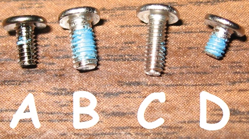
- A - (whole bunch) Bronze-colored, use anywhere I don't say another kind goes...
- B - (4x) Medium length, silver color. For the base of the hinge.
- C - (2x) Longest, silver. Hinge cover.
- D - (4x) Shortest, silver. 2 of these hold the circuit board on, the other 2 go in the raised holes on either side of the board just above it. (Wherever
 points)
- If you lose a screw, use one of the 6 extras in do-nothing screwholes in the handle. There're 3 A's, 1 B, 1 like C but longer (which can also be cut to fit B and C holes), and 1 special wide-head screw.
- When putting the touchpad connectors back, use the thin clear tab to pull them into the connector.
- Note the two little plastic hooks that go through the metal plate, between the keyboard and touchpad. (Not snapping them into place makes the touchpad bulge a bit.)
- Getting the bottom plastic panel on is tough. It has a few L-shaped slide-hooks on the sides and tabs on the bottom. All of these must slide into place at the same time, while bending it slightly to get it past where the rails curve in at the top. Also note that there's a smaller green tab that goes through the middle tab. (Successful installation requires close examination.)

Re sticking the keyboard
It may be necessary to re stick the keyboard, as the glue on the membrane at manufacture is finite. This can be done with some double sided tape, a glass table top(or similar(clean) cutting surface), and a sharp exacto knife.
- Roll off a section of tape, 3/4'ths the length of half the keyboard between the center nub and the outer edge. Use the tape rollers cutter, as you'll want the evenly sized fray pattern it makes on the edge of the tape for measurement purposes.
- With the tape on one thumb, use the exacto knife to position it along the center 'ridge' of the rubber membrane while it is resiting upside down, note how many triangles in the fray pattern, the ridge is wide.
- Place the tape on the cutting surface, using the flat of the tip to get it off your thumb. Now drag the flat of the tip along the tape perpendicularly, every half centemeter or so, so as to hold it flat against the cutting surface.
- Cut off a strip, the number of triangles in the fray pattern that the center ridge was wide(for me, this was 1.5 triangles).
- Lift the strip away from the body of the tape with the flat of the exacto knife and stick it to your index finger.
- Place the tape along the ridge on one side of the center nub sticking it down with the flat of the exacto knife while you roll your finger outwards to unstick it.
- Carefully slide the flat of the exacto knife along the tape to stick it to the ridge.
- Cut another section of tape, and stick it along the ridge at the other side of the center nub.
- Repeat for the ridges above and below the center(in the end you will only need 4 slices of tape, as these top and bottom ridges may have each slice of tape centered)
References
- ticket 495
- Mitch Bradley on #olpc
- Manual/Insides


