Measure/Projects
Contents
Temperature monitoring system
How to build
You need-
- LM35 or any similar temperature sensor
- USB connector
- Audio connector
- Some wire or a cable. You could use cut a USB cable and an audio cable from the middle
- Measure Activity
The USB port has two pins which are of use to us. One is the ground and the other one is the one which provides a constant 5V. When you cut a USB cable in the middle, you could find out by trial-and-error by using a simple Voltmeter which are the two wires corresponding to these two pins. If you don't have a Voltmeter, try using a simple LED and a resistor to do the job.
We provide the +5V that this temperature sensor requires from the USB port. For this we connect the +5V wire to the Vcc of the sensor. We connect the ground to the Ground terminal on the LM35. We connect the Vout of the sensor to the Audio Input jack.
How to operate
Set the Measure Activity to be in the DC Mode and Turn Off the Bias Voltage. Both these can be controlled by using the first two buttons on the 'Measure Toolbar'.
The DC voltage is proportional to the temperature . The voltage that the XO can read varies between 0.9 V - 3V. The output of the sensor would be from 0-5V, so, for for different ranges of temperature one can either use a potential divider for higher ranges or using resistances add a bias to the Vout of the sensor from the +5V of the USB again.
Learn More
The LM35 has an output voltage proportional to the temperature. The scale is 0.01V/C. Read the [Data Sheet] to learn more.
One could log temperature over a period of time - say at an interval of 1 hour for a complete day to know when is it the hottest / coldest.
Video
(put video with flame demonstration here, put pictures here - including ckt diagram)
Intrusion Alarm system
How to build
You need-
- A toy laser
- An LDR or a Photo-Voltaic cell
- Some wire
- Measure Activity
Open up the toy laser and remove the batteries. Connect a wire to the spring inside and connect the other wire to the metallic body inside. Connect both of these wires to the USB power supply wires. Click here to learn about how to determine the USB power supply lines.
Connect the LDR to the Audio Jack.
How to operate
Set the Measure Activity into DC Mode and turn ON the bias voltage. Setup the LDR and the laser to be in line and facing each other. When the path of the laser light gets cut, you should observe a marked increase in voltage indicated by the position of the waveform shifting up.
Learn More
The resistance of the LDR - Light Dependent Resistor is proportional to the amount of light falling on it. The potential drop across the LDR is dependent on the resistance of the LDR. When the path of the light gets cut, the resistance increases hence we notice a marked increase in voltage indicated on the screen.
Click here to know more about Bias Voltage and how it works.
Simple isolation and protection amplifier v2 (version 2)
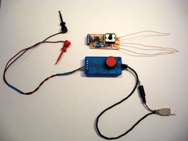
The following "probe-circuit" allows the student or teacher to "input" both DC voltages greater than +5.0 volts (such as from a 9 volt battery, etc), negative voltages, as well as AC voltage. The probe provides resistive isolation of the laptop from what is being measured (the amount of isolation dictated by the choice of two resistors R1 and R2).
A cost-reduced version v3 (difficult target: less than $10.00 in singles and $5.00 in 100's) will forthcoming; it uses a Bourns 3310 potentiometer at 1/2 cost and smaller size so the pc board can be reduced in cost. A fancier version of v2 with a "zero" button (locates the center trace) has been prototyped; it will add about $1.00 in parts (same size circuit board as v2). A yet-fancier version with at least two switchable gains is also under consideration.
- See revision history at bottom of this section.

Specifications
These specifications are valid given use of the preferred components as listed in the Bill of Materials for a 50:1 divider probe, R1 = R2 = 1 megohm, R3 = R4 = 20K ohms, unless otherwise noted:
- Signal-input plug: mono audio plug (3.5 mm, 1/8") (stereo plug will work too -- connect both inputs together)
- Power-input plug: "naked" USB connector -- A-type 4 pin -- with plastic "boot"
- +5 volt power source -- derived from the laptop's USB port (red and black wires inside a sliced-open USB cable)
- +5 volt current draw -- a few milliamperes (less than 5 milliamperes)
- Minimum power-source voltage -- approximately +4.0 volts [as low as +3.0 volts is possible].
- Voltage Gain: R2/R1 (i.e. the circuit divides the input down by this ratio). 1 meg/20K = 50:1
- Laptop settings: Set MEASURE to DC and OFFSET to OFF
- No harm will result if these setting are wrong, e.g. the activity starts in MEASURE = AC. The gain will be higher in AC, but this probe can be used in AC too.
- Common-mode input impedance: 1 megohm each side to circuit common
- Differential-mode input impedance: twice the common-mode impedance
- Maximum input voltage -- tested to 120 VAC. 240 VAC test TBD.
- The components as specified -- in particular R1 and R2 = 1 megohm 500 volt resistors -- are adequate for the task. However, this also assumes a correctly-fabricated and designed pc board with adequate clearance and creepage distance (i.e. tracking-distances across the pc board) between the + and - inputs, R1 and R2 circuit "pads" at their "input" ends, and conformal coating both sides.
- Measureable input voltage: See also AC and DC common-mode rejection specifications. The "gain slider" is the adjustment on the right-hand side of the screen. The trace is adjusted to center-screen and then voltage applied to the (+) and (-) probe inputs; the voltage is adjusted until the trace moves to fully up (+ voltage), or down (- voltage):
Gain of 1/100, i.e. R1 = R2 = 1.00 megohms 0.1%, R2 = R3 = 10.0K ohms 0.1%:
| Gain slider | Maximum +V input, volts | Maximum -V input, volts | Volts per major division |
| Full up | 0.367 | -0.368 | approx 0.050 |
| 75% up | 2.126 | -2.036 | |
| 50% up | 13.13 | -12.62 | |
| 25% up | 78.5 | -73 | |
| 12.5% up | 80 | -80 | approx 10 |
Gain of 1/50, i.e. R1 = R2 = 1.00 megohms 0.1%, R2 = R3 = 20.0K ohms 0.1%:
| Gain slider | Maximum +V input, volts | Maximum -V input, volts | Volts per major division |
| Full up | 0.185 | -0.189 | approx 0.025 |
| 12.5% up | 40 | -40 | approx 5 |
- Input-frequency specification: DC to 10,000 hertz (10 KHz). Beyond this frequency significant aliasing occurs.
- "Aliasing" appears as wiggles on what should be a pure sine wave (an envelope that modulates the input). This is caused by the sampling of the waveform done by the input-converter (codec).
| Trace-speed slider | Minimum frequency | Maximum frequency |
| Right - fast | TBD | TBD |
| Center - medium | TBD | TBD |
| Left - slow | TBD | TBD |
- DC Common-mode rejection: Voltage injected between (i) the two inputs tied together, and (ii) circuit common (circuit 0 volts), tested to +/-90 volts DC.
- DC Common-mode rejection depends critically upon the matching of resistors R1 to R2 and R3 to R4. Matching of ratios R1/R3 = R2/R4 to 0.1% is required.
- AC Common-mode rejection: Measured relative to the power-common (circuit 0 volts), 0-1000 Hz, +6 volts AC rms injected: less than 0.001 volt AC rms (observable at the highest gain setting of the laptop: approx 2 scale divisions)
- AC common mode rejection depends critically not only on the matching of the resistors R1 to R2 and R3 to R4 but also upon stray capacitance in the circuit, the apparent impedance of the reference-voltage source (i.e. the reference-op amp's output impedance), the quality of the op-amps themselves, etc.
Circuit description
This deceptively-simple "probe" circuit is called a "differential amplifer" (differencing amplifier) and although not very fancy it performs the fundamental task of isolating and protecting the laptop from adverse electrical events while allowing the student to measure voltages in excess of +5 volts, minus voltages, etc.
The circuit requires some design tricks and represents some design-challenges, to be described below.
- This circuit has the advantage of not presenting an input voltage greater than +5 volts to the microphone input, plus the USB-port's circuit limits its +5 volt output-current to about 1 ampere in case something short-circuits the USB's output voltage.
- If properly designed, this circuit should survive "accidents" and protect the laptop and the child against such accidents as: "plugging the probe into the 240VAC wall-outlet".
- Any supply voltage derived from another source must be less than +5 volts. For example, three 1.5 volt batteries will also work at +4.5 volts -- as long as the batteries are not accidentally reversed !! -- but four 1.5 volt batteries at 6.0 volts present a risk of inputting more than +5 volts into the microphone input.
- Any externally-derived power voltage (batteries solar cells, etc) directly applied also risks of reveral. If a battery is to be used, add a reverse-protection schottky diode e.g. Avago 1N5711 static-protected by a 0.1 uf capacitor in series with the battery (i.e. a 4.5 volt battery with a 0.4 volt diode drop). A better scheme uses a low-current, +5 volt low-dropout-voltage regulator. Details TBD.
Trick #1 -- "Differential" rather than "single-ended" input: A single-ended amplifer connects one of its two inputs directly to the circuit common -- the metallic part of the USB port, for instance. Any current or voltage on the common goes directly into the laptop. So if somehow such a probe's input-lead is inadvertenly connected to a high voltage, this voltage will appear on the metallic parts of the laptop. If the laptop is electrically isolated, this adverse voltage will present a touch-hazard. If the laptop is electrically grounded, it will be destroyed.
A differential amplifier's two inputs, a "plus" (+) and "minus" (-) are both somewhat isolated from the laptop's common by high-value resistors (true "galvanic" isolation is possible but expensive).
As a properly-designed single-ended amplifier will require use of the same 4 resistors (R1*, R2*, R3**, and R4**) as the "differential" amplifer. Moreover, the differential amplifer subtracts away "common-mode" noise Vn and common-mode voltage Vcm i.e. noise and voltages that appear on both leads (relative to circuit common): i.e.
- ( V(+) + Vn + Vcm) - ( V(-) + Vn + Vcm ) = V(+) - V(-)
So it makes sense to design the amplifer as a differential amplifer.
Trick #2 -- Artificial "ground": This trick kills two problems with one stone. (i) The laptop accepts only positive voltages: The laptop's analog-to-digital converter (codec: AD1888) converts (works only on) plus-DC voltages between approximately +0.3 volts (minimum, corresponding to bottom of screen with high gain (control near the top)) and approximately +2.0 volts (maximum, corresponding to top of screen with high gain (the slider control near the top)). this means that approximately +1.18 volts puts the trace into the center of the screen.
Thus the probe-circuit must "offsets" the difference between the "+" and "-" inputs with this voltage of approximately +1.18 volts. It derives this from a highly-stable "band-gap reference" (any number of different types are possible -- +1.225 volts +/-1% volt, +1.235 volt +/-1%, 2.50 volts +/-1% etc.) Audio-jack inputs less than this "centering-voltage" will drive the trace lower than center, and inputs greater than this "centering-voltage" will drive the trace higher than center. At the laptop's highest gain the voltages require to do this are quite small -- on the microvolt range.
(ii) Increasing common-mode voltage rejection: Together with the choice of R1 and the gain of the circuit, this +1.18 volt offset dictates the maximum common-mode voltage that the probe can "accept" and still function correctly. For example, with R1* = 1 megohm and an attenuation of 1:50 (i.e. the probe reduces the input to 1/50*( V(+) - V(-) ), a negative "common mode" input will be divided down by a factor of 50. If this common-mode voltage V(+) is negative, it will suck out out of the input approximately Vin/(R1+R2) amps, and this will develop a voltage at the input to the amplifier of Vin*R2/(R1+R2)+1.18 volts.
- Example: Common mode voltage is -100 volts, R1* = 1 megohm, R2 = 10K:
- -100*20,000/(1,000,000 + 20,000) + 1.18 = -0.96 + 1.18 or -0.22 volts.
Can the amplifier (LM358AN) tolerate this? Yes, it can tolerate up to -0.3 volts at its (+) and (-) pins. What really happens depends on the circuit design. The part can tolerate up to 50 milliamps being sucked from the (+) or (-) pins. And the resistors prevent any more than a few hundred microamps from being pulled from the pins. So the amplifier will survive.
What about the preferred but expensive LT1413N. In this circuit it can withstand voltages on its (+) and (-) pins equal to the supply voltage (e.g. +5 volts) and -5 volts.
Trick #3 -- Matched decent-quality (i.e. not carbon-film or carbon-composition) resistors: The R1/R3, R2/R4 is called a "bridge" circuit. Its "common-mode rejection ratio" -- the ability of the circuit to reject noise that is on both signal-leads simultaneously -- is determined by the precision of matching of the two resistor-pairs R1/R3 and R2/R4 to 0.1%. The exact R1/R3 and R2/R4 ratio (i.e. 20:1, 50:1, 100:1) is not particularly important, but the two ratios should match to 0.1%. (All four resistors can be matched for very precise division, but the resistors themselves can drift with temperature and time, and the amplifier's input offset will drift, as will the voltage reference). Ideally the resistors should not "drift" too much with temperature; but since they will, at about 25-50 parts per million per degree C (the CMF type), they all should be of the same metal-film construction. The recommended type is a tempertaure-time-voltage-stable (50 parts-per-million) metal-film 1/4 watt resistor such as the Vishay CMF55.
One approach is to buy a bunch of decent resistors (e.g. the metal-film industrial Vishay/Dale CMF or IRC RC55LF-D type available from Mouser at www.mouser.com, a quantity of 100 of 10K cost about $7.00 US, a 1000 cost about $25.00 US) and then sort them into 0.1% categories. Unfortunately this requires a digital ohmmeter. But a trial sort of 100 showed extremely tight matching (+/-0.2% around the nominal). Another approach is to just buy precision resistors (at about 8-to-10x the cost):
- IRC RC55LF-D-10K, 0.1% 25 parts per million per deg C, 1/4 watt at 70C, $0.96 each or $0.64 each in 100's
- IRC RC55LF-D-20K, 0.1% 25 parts per million per deg C, 1/4 watt at 70C, $0.96 each or $0.64 each in 100's
- Vishay/Dale PTF5610K000BYBF, 10K 0.1% 10 parts per million per deg C, 1/8 watt at 85C, max 300 volts @ $0.82 ea, or $0.53 each in 100s
- Vishay/Dale PTF5620K000BYBF, 20K 0.1% 10 parts per million per deg C, 1/8 watt at 85C, max 300 volts @ $0.82 ea, or $0.53 each in 100s
With larger-value resistors R1 = R2 = e.g. 1.0 megohm (the recommendation), measurements with a low-cost ohmeter become problematic and suspect due to phenomena such as test-lead tribo-electric noise. An approach is to sort R3 and R4 to 0.1%, pick an R1 randomly, build a bridge circuit on a plug-in board, and test for R2 matching (the voltmeter goes between R1/R3 and R2/R4. Connect R1 and R2 to a higher voltage supply for more precision -- an acceptable error-reading will be on the order of 0.1 millivolt (100 microvolts).
The recommended procedure, if price is no object, is to buy the precision resistors:
- IRC RC55LF-D-1.0M, 0.1% 25 parts per million per deg C, 1/4 watt @ $1.08 each or $0.72 in 100's
- Vishay/Dale PTF651M0000BXBF, 0.1% 15 parts per million per deg C, 1/4 watt, 500 volt @ $1.68 each, or $1.28 in 100's
Trick #4 -- Use higher-voltage input resistors that can handle extreme overloads : Resistors actually have voltage specifications as well as power specifications. An ideal circuit should survive, and protect the laptop against, 10% high line 230VAC, i.e. 358 volts peak, the common household voltage in much of the world. The industrial voltage 400 +10% VAC 50 Hz i.e. 622 volts peak, or 480 +6% VAC 60Hz i.e. 720 volts peak in the Americas will be destructive). If equipped with 1 megohm, higher-voltage (400-500 volt resistors) input-resistors R1* and R2* in both "legs" of the probe should survive this "household" voltage. This corresponds to 0.07 watts of power, 400 microamps in each resistor common mode. But in fact in differential mode the probe divides this power and leakage in half.
- Example: Common-mode worst case: the laptop power puts earth-ground potential but the probes are both plugged into 230 +10% VAC and this is referenced to the same earth common: (230 +10% VAC)^2/(1,000,000) = 0.105 watts, and 358 volts peak/1,000,000 = 385 microamps into and out of the probe's (+) and (-) inputs and the laptop's common (0 volts of the USB plug).
- Example: Differential-mode worst case: the laptop's power is derived from a "floating" source (e.g. the AC-to-DC adapter provided) but the (-) and (+) are plugged into the 230 + 10% VAC receptacle: (230 +10% VAC)^2/(2,000,000) = 0.05 watts, and 180 volts peak/1,000,000 = 180 microamps into and out of the probe's (+) and (-) inputs.
The tradeoff with larger-value resistors will be more circuit error due to leakage across surfaces, e.g. caused by dust and humidity and their combination. An enclosure together with conformal coating becomes more important. More about this TBD.
Trick #5 -- Pick a decent-quality "centering" adjustment:
- As the laptop warms up the internal reference of the AD1888 "drifts" for about 10 minutes until the voltage stabilizes. This causes the centering to move in one direction or the other.
This has proven to be the most difficult and potentially-expensive part of the design. "Trim-pots" can survive only about 200 adjustments (Bourns specification). A 500 full-cycle test of a Vishay/Sfernice trimpot destroyed it. An adjustment potentiometer that can withstand 25 adjustments a day x 200 days a year x 10 years = 50,000 cycles cost as much as the precision resistors and the amplifer. The favored potentiometers -- a Honeywell pc board-mounted pot and a pin equivalent Bourns pot -- P1 are shown on the Bill of Materials. At least one other manufacturer makes a "pot" that is pin-for-pin compatible.
Trick #6 -- Use only parts that can be hand-assembled: Fewer and fewer parts are designed as "through-hole" with leads on 0.10 inch spacings (2.54 mm), and many very nice parts cannot be hand-assembled because of their tiny sizes.
Trick #7 -- Bend the precision resistors' leads correctly (clamp needlenose pliers between resistor body, then bend lead against needlenose0 and do not apply too much solder-heat -- heatsink with needlenose or alligator clips when soldering : The IRC and Vishay/Dale resistors will drift +/-0.03% (typical) due to soldering. They also don't like physical shock (+/-0.03% typical). Precision components require precision treatment.
Trick #8 -- Ruggedize the mechanical design: The pc board itself is rather rugged. But leads into and out of an enclosure will be subject to stress and strain. Potentiometers will suffer blows. Best practices would either "sink" the plane of a control below the surface of the enclosure or as low as possible (a good example is the laptop's controls).
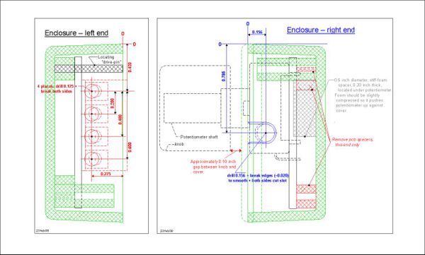
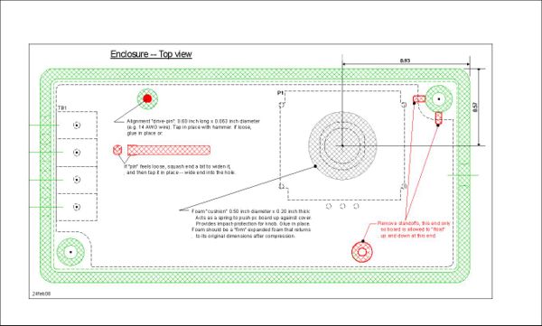
A suggested, alternative design "floats" the pc board inside its enclosure and pushes it (i.e. the potentiometer P1) against the enclosure's lid with a small circle of stiff polyethylene foam. If a child pounds the knob downward, or the enclosure falls on the floor with the knob hitting, there is enough compliance in the potentiometer's shaft to protect it -- the knob hits the lid before the pc board "bottoms out". A sideways blow could be damaging but will probably "flip" the enclosure.
Bill of Materials (BOM)
The following BOM specifies relatively good-quality components and reflect the schematic and the build instructions. Alternate parts are listed.
| Part | Description | Preferred Manuf | Preferred Part Number | Comments | Qty | each, USD | 100 piece price | 1000 piece price | 1-piece price total | 100-piece price total | 1000 piece total |
| C1 | Capacitor: 0.1 microfarad (uf), 10%, 63 V, metallized polyester, 0.20 inch lead spacing, box style | Epcos | B32529C334K | Visay/ Roederstein MKT1817410065 at $0.25/0.18/0.14; AVX BQ014D01044K at $0.11/0.06/0.036 | 1 | 0.17 | 0.066 | 0.046 | 0.17 | 0.07 | 0.046 |
| C2 | Capacitor: 0.33 microfarad (uf), 10%, 63 V, metallized polyester, 0.20 inch lead spacing, box style | Epcos | B32529C334K | Visay/ Roederstein MKT1817433065 at $0.26/0.138/0.077; AVX BQ024D03344K at $0.21/ 0.1125/ 0.0675 | 1 | 0.26 | 0.138 | 0.077 | 0.26 | 0.14 | 0.077 |
| IC1 | IC: Dual op-amp, single-supply 3 volt min, 3 mv max input offset, 30 nA input offset current max, 8-pin DIP | Fairchild Semi, National Semi | LM358AN or LM258AN | ST Micro, Texas Instruments, etc. | 1 | 0.34 | 0.24 | 0.138 | 0.34 | 0.24 | 0.138 |
| LED1 | LED: green clear, 20 millicandela, 2.2V forward voltage, T-1 3/4, 0.1 inch lead spacing | Kingbright | WP7113SGC | Any color, any manufacturer: Avago HLMP-3507 | 1 | 0.13 | 0.10 | 0.07 | 0.13 | 0.10 | 0.07 |
| P1 | Potentiometer, single turn, conductive plastic, PC mount, 10K ohm +/-20%, 50000 cycle life | Honeywell | 574SX1M48F103SD | PC-mount hole pattern is same as Bourns and other manuf. | 1 | 3.10 | 1.68 | 1.445 | 3.10 | 1.68 | 1.445 |
| P2 | Potentiometer, trimmer, sealed, single turn, 1/4 inch cermet, 1K, 10%, 100 ppm/deg C, vertical mount | Bourns | 3362X-1-102LF | Or equivalent staggered pinout e.g. 3/8 inch 3386X-1-102LF or BI Technologies equivalents, Vishay/Sfernice equivalents | 1 | 0.83 | 0.65 | 0.555 | 0.83 | 0.65 | 0.555 |
| R1*,R2* | Resistor: 1.00 meg, 0.1%, 1/2 watt precision, metal film, 10-25 ppm/deg C | Vishay/Dale | CMF601M0000BEEK | first B designates 0.1% | 2 | 0.70 | 0.45 | 0.28 | 1.40 | 0.90 | 0.56 |
| (R1*, R2*) | Resistor: 1.00 meg, 1%, 1/2 watt commercial, metal film, matched to 0.1% | Vishay/Dale | CMF601M0000FHEK | Generic metal film 1%, 100ppm/deg C: RN60D1002F | 2 | 0.18 | 0.15 | 0.13 | |||
| (R1*,R2*) | Resistor: 1.00 meg, 0.1%, 1/2 watt precision, metal film, 10-25 ppm/deg C | Vishay/Dale | PTF651M0000BYBF | also: IRC RC55LF-D-1.0M, 25 ppm, 200 volt,L $0.96/$0.64 | 2 | 1.87 | 1.21 | 0.94 | |||
| (R3**, R4**) | Resistor: 20.0K, 0.1%, 1/4 watt , metal film, 50 ppm/deg C | Vishay | CMF5520B000BHEB | first B designates 0.1%, second B tape-and-reel | 2 | 0.36 | 0.29 | 0.24 | 0.72 | 0.58 | 0.48 |
| (R3**, R4**) | Resistor: 20.0K, 1%, 1/4 watt, metal film, matched to 0.1%, 50 ppm/deg C or better | Vishay | CMF5520K000FHEK | Generic metal film 1%, 100ppm/deg C: RN55D2002F, matched to 0.1% | 2 | 0.14 | 0.07 | 0.055 | |||
| ( R3**, R4** ) | Resistor: 20.0K, 0.1%, 1/4 watt precision, metal film, 10-25 ppm/deg C | Vishay | PTF5620K000BYBF | also: IRC RC55LF-D-20K, 0.1%, 25 ppm, 200 volt: $0.96/$0.64 | 2 | 0.88 | 0.685 | 0.55 | |||
| R3**, R4** | Resistor: 20.0K, 0.1%, 1/4 watt , metal film, 50 ppm/deg C | Vishay | CMF5520B000BHEB | first B designates 0.1%, second B tape-and-reel | 2 | 0.36 | 0.29 | 0.24 | 0.72 | 0.58 | 0.48 |
| R6, R11 | Resistor: 10.0K, 1%, 1/4 watt commercial, metal film, 50 ppm/deg C | Xicon | 271-10K-RC | 2 | 0.09 | 0.02 | 0.012 | 0.18 | 0.04 | 0.024 | |
| R7 | Resistor: 8.45K, 1%, 1/4 watt commercial, metal film, 50 ppm/deg C | Xicon | 271-8.45K-RC | 1 | 0.09 | 0.02 | 0.012 | 0.09 | 0.02 | 0.012 | |
| R8 | Resistor: 20.0K, 1%, 1/4 watt commercial, metal film, 50 ppm/deg C | Xicon | 271-20K-RC | 1 | 0.09 | 0.02 | 0.012 | 0.09 | 0.02 | 0.012 | |
| R10 | Resistor: 499 ohm, 1%, 1/4 watt commercial, metal film, 50 ppm/deg C | Xicon | 271-499-RC | 1 | 0.09 | 0.02 | 0.012 | 0.09 | 0.02 | 0.012 | |
| R5, R12 | Resistor: 1K, 1%, 1/4 watt commercial, metal film, 50ppmdeg C | Xicon | 271-1K-RC | 2 | 0.09 | 0.02 | 0.012 | 0.18 | 0.04 | 0.024 | |
| TB1 | Terminal block: screw-type, 5.08mm pitch, 2 terminal, vertical mount, 10mm height, with clamp | Radio Shack | 276-1388 | Set of 4 x 2-position blocks; 2 blocks lock together | 0.5 | 2.49 | 1.25 | ||||
| (TB1) | Terminal block: screw-type, 5.08mm pitch, 2 terminal, vertical mount, 10mm height, with clamp | Molex | 39880-0302 | 2 | 0.55 | 0.29 | 0.26 | 0.58 | 0.52 | ||
| (TB1) | Terminal block: screw-type, 5.08mm pitch, 4 terminal, vertical mount, 10mm height, with clamp | Phoenix Contact | 1729144 MKDSN 1.5/4-5.08 | 1 | 1.44 | 1.09 | 0.92 | ||||
| Z1 | 2.50 volt 1% shunt regulator/reference, TO-92 | Texas Instruments | TL431ACLP | Any equivalent | 1 | 0.40 | 0.27 | 0.135 | 0.40 | 0.27 | 0.135 |
| Total | Total | Total | 9.95 | 5.92 | 4.59 | ||||||
| PCB | PC Board: 0.062 inch glass-epoxy FR4, 1 oz copper two sides, plated-through holes, 2.913 x 1.330 inch, 67 holes standard sizes, no solder masks or component identifiers | AP Circuits | --- | For budgetary (estimation) purposes | 1 | 4.97 | 3.34 | 4.97 | 3.34 | ||
| (PCB) | 2-sided phenolic double-sided copper 0.062 | Radio Shack | 276-1499 | Yields qty 6 boards: $4.50 + cost of drill ($2.00) + cost of burr ($4.00) divided by 6 | 1 | 1.65 | 1.65 | ||||
| Case & lid | Plastic, translucent blue: 3.150 x 1.575 x 0.787 inch | Hammond Manufacturing | 1551KTBU | 1 | 1.84 | 1.32 | 1.19 | 1.84 | 1.32 | 1.19 | |
| knob | Knob diameter TBD -- for best fit knob requires "skirt recess" of 0.11 inch, 0.5 inch shaft depth, knob height approx 0.65-0.75 inch | Rogan | PT 5-S | Rogan knob requires shortening shaft, and clips in place. Use Radio Shack knob for lower-quantity pricing. | 1 | 0.75 | 0.75 | 0.75 | 0.75 | ||
| knob | 2-shot black and grey, no markings, 0.62 diameter, 0.45 high, for D-shaft 0.25 long. With spring clip for 2.50 x .218 shaft. | Rogan | PT-5-S | Rogan knob requires shortening shaft, and clips in place. 10K pricing drops to $0.36 | 1 | 0.59 | 0.59 | ||||
| knob | 0.625 diameter skirt, 0.25 shaft diameter, | Handmade | www.grainger.com supplies the material | Approximately 100 knobs can be made from a 6 ft long ABS rod at $15.71, $5.02 for PVC Type 1 grey, UHMW-PE Black 5.8 in dia $6.01 | 1 | 0.10 | |||||
| Sub-total | Sub-total | Sub-total | 4.34 | 7.04 | 5.12 | ||||||
| PL1 | Plug, mono audio 3.5 mm (1/8 inch), black plastic barrel and strain relief | CUI Inc | MP3-3501 | Has somewhat flexible strain relief | 1 | 0.76 | 0.51 | 0.38 | 0.76 | 0.51 | 0.38 |
| (PL1) | PL1: Plug, mono audio 3.5mm (1/8 inch), black plastic barrel | Kobiconn | Mouser 171-PA-3191-1-E | Generic | 1 | 0.71 | 0.50 | 0.42 | |||
| PL2 | USB plug: "silver/white", A-type 4 pin, "naked" (no attached wires) | Kobiconn | Mouser 154-UAW16-E | Assmann A-USBPA-R: $0.40/0.24/? | 1 | 0.68 | 0.42 | 0.35 | 0.68 | 0.42 | 0.35 |
| PL2 | USB plug-hood: for Kobiconn 154-UAW-16-E | Kobiconn | Mouser 154-UAC16-E | Acts as a strain relief. Assmann A-USBPA-HOOD-R $0.36/0.22/? | 1 | 0.54 | 0.33 | 0.27 | 0.54 | 0.33 | 0.27 |
| test-lead wire | RED PVC insulation, 28 AWG 19x40 stranding, 0.018 inch insulation, 0.047 inch total diameter. | www. e-z-hook.com | 9501-100-red; 9501-1000-red | 4 | 0.228 | 0.228 | 0.16 | 0.912 | 0.91 | 0.64 | |
| (test-lead wire) | RED PVC insulation, 300V, 28 AWG 7x36 stranding, 0.018 inch insulation, 0.047 inch total diameter. | Alpha | Alpha UL1007 | 4 | 0.225 | 0.225 | 0.108 | ||||
| test-lead wire | BLACK PVC insulation, 28 AWG 19x40 stranding, 0.018 inch insulation, 0.047 inch total diameter. | www. e-z-hook.com | 9501-100-black; 9501-1000-black | 4 | 0.228 | 0.228 | 0.16 | 0.912 | 0.91 | 0.64 | |
| (test-lead wire) | BLACK PVC insulation,300V, 28 AWG 7x36 stranding, 0.018 inch insulation, 0.047 inch total diameter. | Alpha | Alpha UL1007 | 4 | 0.225 | 0.225 | 0.108 | ||||
| heatshrink | Very-flexible polyolefin 1/4 inch final diameter, black | 3M | VFP-876 1/8" x length, black | $2.49 per 5', $28.53 per 100', $103.01 per 500' | 1.8 | 0.498 | 0.2853 | 0.103 | 0.90 | 0.51 | 0.1854 |
| heatshrink | Very-flexible polyolefin 3/32 inch final diameter, black | 3M | VFP-876 3/32" x length, black | $2.31 per 5', $26.45 per 100', $95.48 per 500' | 0.5 | 0.46 | 0.265 | 0.191 | 0.23 | 0.13 | 0.0955 |
| heatshrink | Very-flexible polyolefin 3/16 inch final diameter, black | 3M | VFP-876 3/16" x length, black | $3.03 per 5', $30.70 per 100' | 0.1 | 0.606 | 0.307 | 0.307 | 0.06 | 0.03 | 0.0307 |
| heatshrink | Flexible polyolefin 3/32 inch final diameter, RED | 3M | FP332R x length | $1.92 per 5', $22.03 per 100' | 0.15 | 0.384 | 0.220 | 0.220 | 0.06 | 0.03 | 0.033045 |
| strain relief C-ring | Crimp-ring: 0.125 inch inner-diameter, 14 AWG (0.062) copper or aluminum wire | Handmade | --- | Wind e.g. 16 turns on .125 inch steel mandrel, grind a slot through all turns simultaneously (use 2 abrasive Dremel grinding wheels on Dremel arbor) -- makes 16 C-rings | 2 | 0.01 | 0.01 | 0.01 | 0.02 | 0.02 | 0.02 |
| Foam cushion | 0.125 thick, approx 0.5 inch diameter | Seattle Fabrics | TBD -- stiff polyethene foam | For knob compliance (impact protection) -- glue beneath pot P1 | 1 | 0.01 | 0.01 | 0.01 | 0.01 | 0.01 | 0.01 |
| Foot | Surface-gripping foot | ||||||||||
| Sub-total | Sub-total | Sub-total | 5.08 | 3.82 | 2.65 | ||||||
| Total | Total | Total | 19.36 | 16.78 | 12.36 | ||||||
| Optional | |||||||||||
| minihook | Standard construction, square-hole tip, "minihook" to minihook, 36 inches red 22 AWG 66x40 | www. e-z-hook.com | 204-36W-red | $4.32/3.90/3.25 divided by 2 | 1 | 2.16 | 1.95 | 1.62 | 2.16 | 1.95 | 1.62 |
| minihook | Standard construction, square-hole tip, "minihook" to minihook, 36 inches black 22 AWG 66x40 | www. e-z-hook.com | 204-36W-BLK | $4.32/3.90/3.25 divided by 2 | 1 | 2.16 | 1.95 | 1.62 | 2.16 | 1.95 | 1.62 |
Oscilloscope probe construction details
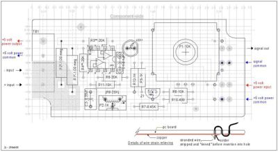
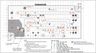
PC board manual-construction details
The following is the recommended construction method:
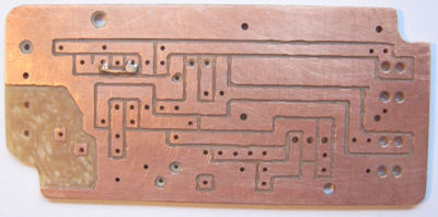
- Crude point-to-point wiring on a piece of "perf" board (unplated PC board material perforated on 0.1 inch spacings) exhibits "AC pickup" (capacitively-coupled interference between the student's hand and the components and traces of the pc board). For this reason, this method was abandoned in favor of a two-sided pc board either hand-fabricated with top- and bottom-soldering, or a commercially-fabricated as a double-sided plated through-hole pc board.
Construction method: Start with 0.062 inch thick, double-sided 1 oz copper (1/2 oz will work in a pinch, so will 0.032 inch thick double-sided) pc board laminate. Radio Shack's pc laminate is a cheap melamine/phenolic material but it contains no glass fibers to wear out your drills and Dremel burrs. The more classical and rugged substrate is "FR4" ("Fire Resistant") glass-epoxy (available from www.digikey.com or www.mouser.com).
To hand-fabricate such a board, tools required include a digital voltmeter, a steel dial calipers (to act as a ruling scribe as well as a measuring device), a Dremel tool (high-speed hand-held rotary tool) mounted in a "drill press" (Dremel and Sears sells them) and quipped with a 0.032 inch drill etc. (beaders/jeweler's drills work nicely), safety glasses (required for careful observation while drilling and soldering), soldering iron with pointy tip, thin flux-core solder with rosin or other activating agents in the solder, solderwick, needlenose pliers, miniature flush cutters, a wire stripper, etc. Tape and a small vise or other holding device (e.g. for fishermans' fly-tying) are very useful.
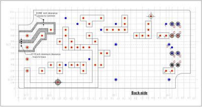
If the builder has access to a decent inkjet printer then with some "dimensional adjustments" (i.e. trial and error, but it must be accurate!) the images could be printed onto good-quality paper and stuck -- with double-sided tape (glue won't work) -- to the raw pc board. Drill the two B-holes from the front side (top, component side). Drill the same two B-holes into the backside (bottom) image. With the use of two locator "pins" (e.g. headless nails driven into a piece of soft wood and located with the help of the pc board's locating holes) put the backside image face down (oriented correctly!); you will eventually drop the pc board down on the locator pins. But first apply the double-sided tape to the back of the pc board, and drop the board down onto its back (bottom) image. (If this is done well, three or four boards can be stacked and drilled all at once.)
- Drilling should be done with the Dremel tool set at about half to 3/4 of full speed, i.e. much faster than a drill press. If the drills are sharp and the speed is high, the holes will be very clean. Do not apply a lot of drilling pressure, expecially when drilling stacked boards (the drills may "wander" in the stack).
Another approach is to use a dial caliper's sharp points to rule a 0.10 inch grid over the surface of the black pc board. Carefully locate and mark each hole with a prick-punch (a sharpened steel nail will do). Then drill the holes.
Now remove the etch to form the traces -- don't go too deep, go back and forth a few times to remove just the littlest amount of copper. This is straightforward but tedious work when the image is stuck to the board. Otherwise, use a very fine indelible marker to draw where the copper is to be removed. and then remove etch with a Dremel tool -- the trick is to remove, with a tiny Dremel burr (#106 0.032 burr is best, a #107 0.062 burr will work in a pinch), as little etch as possible. Use a cork-backed, stainless steel ruler as a guide for both the marking pen and when cutting the etch away with the Dremel tool. If the copper is tinned, so much the better -- bare copper will tarnish; although this does not affect the circuit, soldering is more difficult.
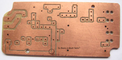
After removing the scraps of paper+tape, if used, clean up the board with very very fine sandpaper or steel wool. Inspect it against a very bright bulb for tiny (hairline or smaller) bits of shorting copper. (This is mandatory: It's almost impossible to aviod tiny shorts. Use the Dremel tool with the tiny burr to double-check all the grooves you've cut in the board.)
Kits exist to etch pc boards. See www.mouser.com or www.digikey.com. A commercially-fabricated pc board is preferred. (Details TBD). The following book is excellent -- Al Williams, 2004, Build Your Own Printed Circuit Board, McGraw-Hill, New York, ISBN0-07-142783-X. The book includes a free-ware CD (Eagle software) for Windows or Linux that permits schematic capture and double-sided pc board layout.
Lead-bending: Always use a needlenose pliers between the body of the part (e.g. resistor) and the lead to be bent.
Solder overheating, cold-solder joints, etc: This double-sided fabrication requires both top and bottom soldering -- mandatory for all but those few components with leads that cannot be reached (pot P2, LED, capacitors C1 and C2, and Z1). Be sure to use a fluxed solder specifically for electronics work (do not use plumber's acid-core solder). Practice your soldering technique. The components can take a few seconds of soldering heat. But prolonged application of heat, or the use of huge soldering tips (e.g. don't use a soldering "gun"), and monster blobs of solder will overheat the matched resistors R1 and R2, R3 and R4, the voltage reference Z1 and the operational amplifer IC, cause shorts, melt away the PVC insulation of the lead-wires, etc. Be on the lookout for "cold-solder" joints -- places where the solder doesn't flow nicely and leaves the connection "unmade".
Cleanup: If you use rosin-fluxed solder the rosin is left on the board. The best practice is to remove it; start by scraping it out of the bare places between the copper and then apply isopropyl alcohol (rubbing alcohol e.g. 70% isopropyl/30% water) with a cheap bristle paintbrush. (Or use a professionally-compounded mix). Don't dip into the solvent or water-wash this board! The big potentiometer is not sealed! And gunk may get into the terminal block. Some water-soluable fluxes exist, but again, use a brush to apply any solvent. Or use a no-clean flux.
- After brushing on the alcohol mount the board vertically and at an angle so that the gunky liquid drains off the lower left corner.
Conformal coating: Manufacturers use sprays (expensive) to "conformally coat" their boards for water-, dust- and fungus-resistance. Use multiple coats. See www.mouser.com or www.digikey.com. Be careful to tape over the output terminal block TB1 and any "entry points" of potentiometer P1.
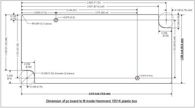
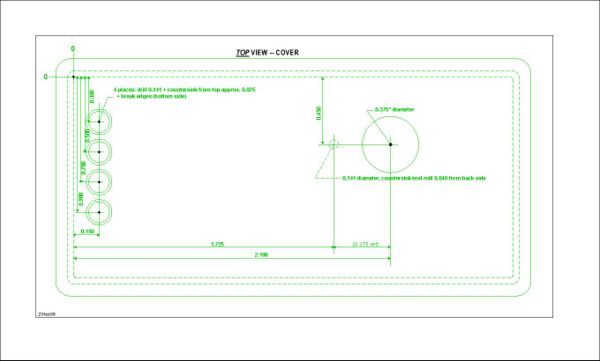
Assembling into a box, potting: The assembly should be put into a little plastic box. "Potting" (casting the board in a compatible 2-part RTV rubber) would be ideal excepting that the potentiometer P1 will "leak" and be ruined, and once potted the circuit may not be repairable, and the compounds are expensive. The better alternative is to conformally-coat the board (apply masking tape over the place where P1's leads exit, and over the top and side of terminal block P1) and then enclose in the suggested box (more measuring and drilling is required). See mechanical details below.
Best practices: The most difficult part of the design is how to assemble it into a robust object suitable for use by children. The current recommendation is to have the board loose (somewhat -- 0.015 inch on each side) in the box but pushed up against the cover by a 0.5 to 0.75 inch diameter x 0.20 inch thick circle of stiff polyethylene foam. The knob should have just enough clearance so if a child pushes hard on the knob the whole board is pushed into the box, but then springs back and pushes the board up into position. (2) Wires into the USB and audio plugs must be strain-relieved by bending-over of the "prongs" onto heatshrink tubing over the wires (the heatshrink tubing protects the wires). (3) A strain relief for the wires into the box must also be provided. See details below.
Cable: For +5 volt power from laptop and audio-plug input to laptop
A detailed description of the cable between the circuit and the laptop:
- Step 1 Assemble the components.
- Step 2 Form the USB twisted pair and audio twisted pair:
- 2.1 Cut 2 lengths of red wire at 24 inches, cut two lengths of black wire at 24 inches. Twist together at approximately 0.5 turn per inch. These form the +5 volt/USB pair and the audio-plug pair. The twisting will shrink the wires about 1 inch in length. Tag (tape, or solder, etc) the pairs to keep them straight.
- 2.2 Form a single cable from the two pairs: Start with all four wires flush at the left end. Then cable the two twisted pairs together into a smooth bundle of four wires. Cut the USB pair so it is 5 inches shorter than the audio pair.
- 2.3 Fish the cabled pairs down the 16 inch length of 0.187 inch (beginning-diameter) heatshrink tubing. For example, run a piece of 24 inch solid (stiff) wire to the left end of the cable and pull the cable through the heatshrink. Start with the tubing 1.5 inches from the left ends.
- 2.4 Place the 4.0 lenth of 0.125 (beginning diameter) heatshrink tubing over the audio plug twisted pair. Important: Space this tube about 0.25 inch away from the end of the first heatshrink tubing. This will leave the 0.25 inch of audio-plug wire exposed for purposes of bending in the following step.
- 2.5 Shrink the tubing: Start at the left end and use a heat gun to shrink the tube over the cabled wires (air from a hair-drying gun may work, but is usually not quite hot enough). Or carefully rub the barrel of a hot soldering iron (not the tip) over the length of tubing (takes practice, dwelling too long will melt the wires and/or destroy the heatshrink tubing).
- 2.6 Trim the USB cable so it extends at 0.5 inches beyond the end of the cable+heatshrink. Carefully: Strip the red and black wires back 1/8 inch and "tin" with solder. (If mistakes are made, you will have to clip back the heathsrink over the cable and try again.)
- Step 3: Solder the USB plug to the cable:
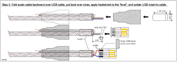
- 3.1 Form the "pigtail" or "knot": Bend the audio-plug pair backward along the two-pair bundle. Cut a 0.75 inch piece of 0.25 heatshrink tubing (0.25 inch diameter before heathrinking) and place over the bend, covering it. Heatshrink this tubing in place. This "knob" or "knot" will receive the crimp of the USB connector -- i.e. the crimping of the jaws will occur over this "knot", thereby strain-relieving both connectors.
- 3.2 Slip the USB plastic "boot" over the right end (over the 4-wire bundle and the 2-wire bundle), wide-end to the right.
- 3.2 Solder the USB connector to the USB pair of wires (in the following, the mechanical equivalent of an extra pair of hands such as fly-tying holder -- will be very helpful).
- 3.2.1 The "knot" must be about 1/8 inch inside the crimping zone so that the crimps will fall solidly over the "knot". From this criming zone measure out 0.5 inch and cut the USB wires flush. Strip back 3/16 inch (0.187 inch, 4.8 mm). Tin the wires.
- 3.2.2 Tin the two outer-most contacts on the USB connector's white insert.
- 3.2.3 Solder the red wire to the uppermost and the black wire to the bottommost contact of the white insert.
- 3.2.4 Inspect your workmanship carefully. If the solder is blobby and ugly, or any loose solder is on the insert, or little wires are loose, trim them away with a sharp knife (e.g. an Xacto tool).
- 3.2.5 With careful attention to orientation, snap the little black clip in place. If it doesn't fit, you may have put too much solder on the terminals. Fix any problems.
- Step 4: Assemble USB plug
- 4.1 Insert the white insert "upside down" in the larger, outer metal shell. The insert should slide easily into the shell; if not you're inserting it upside down.
- 4.2 Snap the smaller metal shell/cover over the larger metal shell to cover up the wires .
- 4.3 Carefully (workmanship counts here) crimp the "teeth" of the jaws over the "knot". Be sure not to crimp too hard, but make the crimping neat and tidy and firm, round as possible, and make sure the jaws are closed and the teeth mesh. Test with tug.
- 4.4 Rotate the boot so that its little USB symbol is on the unjointed side of the metal connector, then slide it forward over the knot (may be a bit of a tight fit) and continue sliding it forward until it clicks in place.
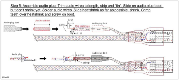
- Step 5 Mount the audio plug to the audio-plug pair of wires (again, the fly-tying holder will be a help here):
- 5.1 Disassemble the audio plug's boot from the plug and slip it, narrow end first, over the audio wires.
- 5.2 Cut a piece of red 3/32 inch heatshrink 1.25 inches long and slip this over the wires.
- 5.3 With the red heatshrink flush to the black heatshrink, heatshrink this red tube in place. This red tube will be acting as both a marker -- red plug into red jack of laptop -- and as a wire protector.
- 5.4 Cut the red wire 3/8 inch from the end of the two heatshrink tubes, and strip it back 1/8 inch or a bit longer if using a stereo plug.
- 5.5 Cut the black wire 1/8 or less from the end of the two heatshrink tubes, and strip it back 1.8 inch.
- 5.6 Tin both wire-ends. Thin the connector's terminals being sure to keep the holes open -- the black-wire solder joint will be underneath the "tang".
- 5.7 Solder the red wire through the terminal(s) (Through both terminals if the plug is a stereo plug).
- 5.8 Pass the tinned black wire through the hole in the long "tang" and solder it to the underside tinned area.
- 5.9 Inspect your workmanship for cold solder joints, blobs, messiness, loose strands of wire, etc.
- 5.10 Carefully (again, workmanship counts here) crimp the "teeth" of the jaws over the heatshrink. If the jaws are over the wires, redo the job. Be sure not to crimp too hard, but make the crimping neat and tidy and firm, relatively round, and make sure the jaws are closed and the teeth mesh. Test with a tug.
- 5.11 Screw the "boot" over the plug and tighten firmly but not so tight that you strip the threads.
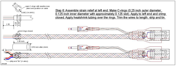
- Step 6 Strain-relieve the circuit-board end (left end) of the cable:
- 6.1 Place a C-crimp 1/4 inch from the end of the heatshrink tubing. As before, carefully crimp the C closed. Be sure it is firmly grabbing onto the wire -- test by tugging.
- 6.2 Place a second C-crimp 1/8 inch from the first one. (Measure this, it's important). Crimp this C closed. test by tugging.
- 6.3 Cut a piece of 1/4 heatshrink to 1.0 inch and slip over the two C-crimps so that that it is flush with the heatshrink that is already there.
- 6.4 Heatshrink the tube in place.
- 6.5 Test the cable and prepare it for attachment to the pc board: strip back the four ends 3/16 inch and tin, but keep track of which pair is which (with tape etc). Test continuity with an ohmmeter (i.e. a digital voltmeter in the "Ohms" setting).
Mechanical construction details
Revision History, simple differential amplifier
The design is subject to revisions as it evolves.
- REV 0: Prototype-test phase, redraw "layout" drawings, add info re E-Z-Hook to schematic & remove top-view symbols (2 Jan 08)
- REV 1: Correct "layout" drawing -- change potentiometer symbol from bottom to top view (3 Jan 08)
- REV 2: Change gain from 1:10 to 1:20, show optional components on schematic with . Add 2nd layout drawing for single-turn potentiometer implementation, plus an LED power-on indicator. Update Bill Of Material. (5 Jan 08)
- REV 3: Extensive revision of Bill of Materials with added 1000-piece price estimates, modified circuit schematic with terminal block and second "rough trim" potentiometer, modified assembly and layout drawing, new cable-assembly method, etc based on experience of two hand-built prototypes (12 Feb 08).
- REV 4: Correct mistakes in schematic. Add preliminary cable-assembly drawings (19 Feb 08). Add photograph of prototype #2 and pc board #3 (20 Feb 08).
- REV 5: Add mechanical construction drawings. Emend cable-assembly drawings. Emend hand-fabrication instructions (24 Feb 08).
- REV 6: Add new layout prints and photographs. Emend hand-fabrication instructions (27 Feb 08). Update B.O.M. (6 March 08). "v2" design is considered completed.
Other ideas
- A low cost (possibly $2) probe that would increase the range of voltage that can be applied to the input.
- An ultrasonic distance measurement system that connects to the XO and allows the XO to log data. This has immense applications in water level monitoring in villages and also in robotics applications.
- A general purpose hardware kit that interacts with the measure activity. Something on similar lines to http://www.create.ucsb.edu/~dano/CUI/
- Sensors could be distributed along with the XO as peripherals. The advantage of this would be that the measure activity can be calibrated against the known specs of the sensors.
- Being able to measure resistance
- A low cost version of LEGO mindstorms system built around the XO. The XO has good hardware and software capabilities to achieve this.
- RS232 or serial interface would allow a host of electronic devices to interact and communicate with the XO.
- Build a sensor network using a sensor connected to each XO and utilize the mesh networking capability of the XO. This would give us a highly powerful, robust and reconfigurable sensor network.
- Build medical applications using sensors and the XO. See TeleHealth_Module
- Do some Fablab projects using the XO. See http://fab.cba.mit.edu/labs/vigyan/
- Collaborative music creation over the mesh using the music software on the XOs and giving input from an array of different sensors.
- Integrate sensor input into LOGO / Turtle activity
- Milk purity in rural areas. I remember reading about it in some FabLab's website - I think it requires an ADC, which we have.
- Making a battery out of some vegetable (potato, onion?) to study electricity and current.
