Mppt
Maximum Power Point Tracking
When running the laptop from a power source with a non-linear source resistance, such as a photovoltaic solar panel, it is difficult to extract the maximum power available from the source.
The power output of a solar panel is related to insolation; the amount of sunlight hitting the panel.
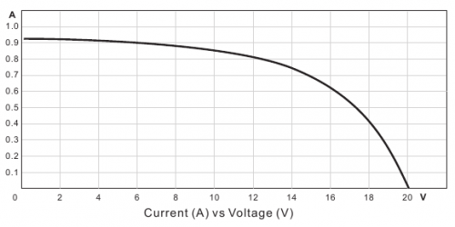
But the voltage output of a solar panel is related to output current. The Current-Voltage curve for the OLPC panel, typical for almost all solar panels, at a specified insolation, is:
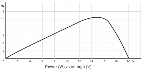
As the current draw increases from the panel the voltage decreases. This creates a power curve that looks like this, again at a specified insolation:
So there is an optimum input voltage for obtaining the maximum power.
But when insolation changes there is another curve. So the optimum input voltage varies with the amount of sunlight hitting the solar panel, and this must be tracked in real-time.
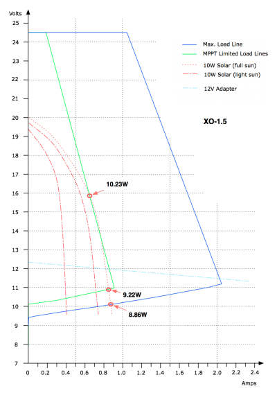
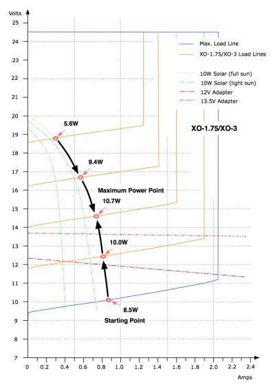
In the following Voltage-Current plot, the dark blue line shows the input impedance of the laptop (with the MPPT control at maximum input power). The red lines show the output impedance of a typical solar cell, with different levels of insolation. The light blue line shows the output impedance of a typical XO power supply.
With no maximum power point tracking (MPPT) algorithm running, the load lines intersect at the bottom point, giving an input power of 8.86W. With MPPT running, it is possible to move the intercept point by increasing the input impedance of the laptop to obtain 10.23W from the solar panel in the same situation.
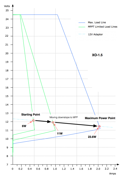
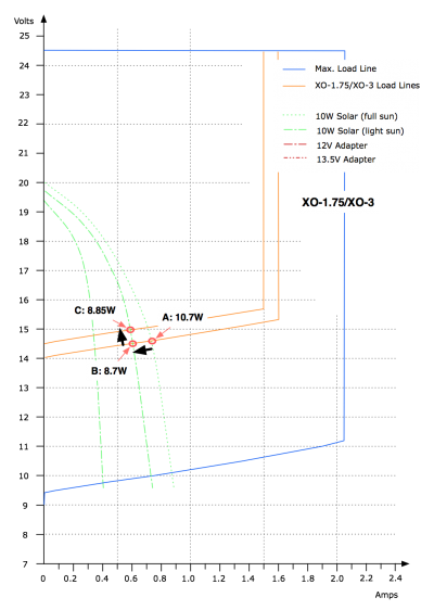
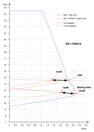
OLPC has used two different mechanisms for regulating the input impedance of the laptop. One which just limits the maximum input current of the laptop was used in XO-1/1.5, and another which controls the minimum input voltage will be used in XO-1.75/XO-3.
XO-1.5
XO-1.75/XO-3
EC MPPT algorithm
Overview
This describes the MPPT algorithm present in the XO-1.5 embedded controller. When operating from a PV solar panel the available power can be very dynamic even in seeming very sunny conditions. In many cases the maximum power available from the solar panel is less than the maximum power draw of the XO-1.5. The maximum power input to the XO-1.5 is 25W but the most common OLPC solar panel in use is only rated at 10W. This can create up to a 15W power deficit.
Definitions
- Pin
- Power input to the XO-1.5.
- Psystem
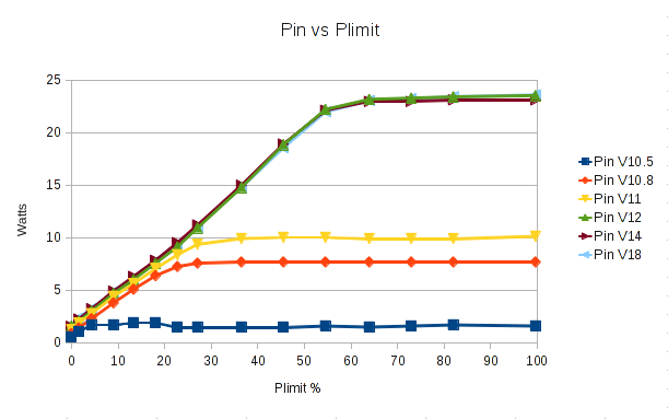
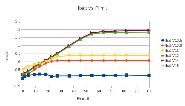
- Amount of average input power that results in an average battery current of zero or very near zero. Empirically determined on an XO-1.5 to be about 7W average if the system is doing work.
- Plimit
- The charger power limit % that corresponds to Psystem. Empirically determined to be 20%.
Psystem and Plimit Data
Squeal Detect
Squeal Detect is the ability of the EC to detect when the system is attempting to draw much more current than the PV source can provide. When this happens the external power good pin can start to oscillate. It usually oscillates in the audible range and the inrush currents into the inductions produce an audible "squeal". The squeal detector watches this pin and indicates when its oscillating.
Assumptions
TODO:
Flow Chart
Wikimedia seems to hate trying to render my .svg . Here's a link to the .svg file Media:mppt.svg
The dia file is also available.
And here's the same thing as pdf:
