Notes on using the OLPC developer boards/lang-ja
- This is an on-going translation
Community Notes
The Getting involved in OLPC page has information about OLPC, mailing lists. Real time help can often be had on the #olpc channel on irc.freenode.net. Most of the hardware and driver discussions should take place on the devel list. If this becomes a problem, we'll split lists to finer topics as needed. There are a number of other OLPC lists on various topics (e.g. security, networking). OLPC Fedora distribution specific questions should go to that list.
The Fedora source repository has the Fedora distribution being developed for OLPC.
In general, work in the upstream projects whenever possible. Laptop.org is also able and willing to host projects, but we will get quite grumpy you ask to host projects that are effectively forks of other upstream projects without extremely good justifications.
Additionally, git repositories of drivers under development before they go upstream to Andrew Morton / Linus Torvalds are being hosted by Dave Woodhouse at git://git.infradead.org/ (browsable in gitweb).
Getting Developer Boards
The Developers Program has information on how to get developer's boards.
Please read this note carefully and through the end before using the boards. Putting a "watch" on this page will inform you of any important changes.
Hardware Notes
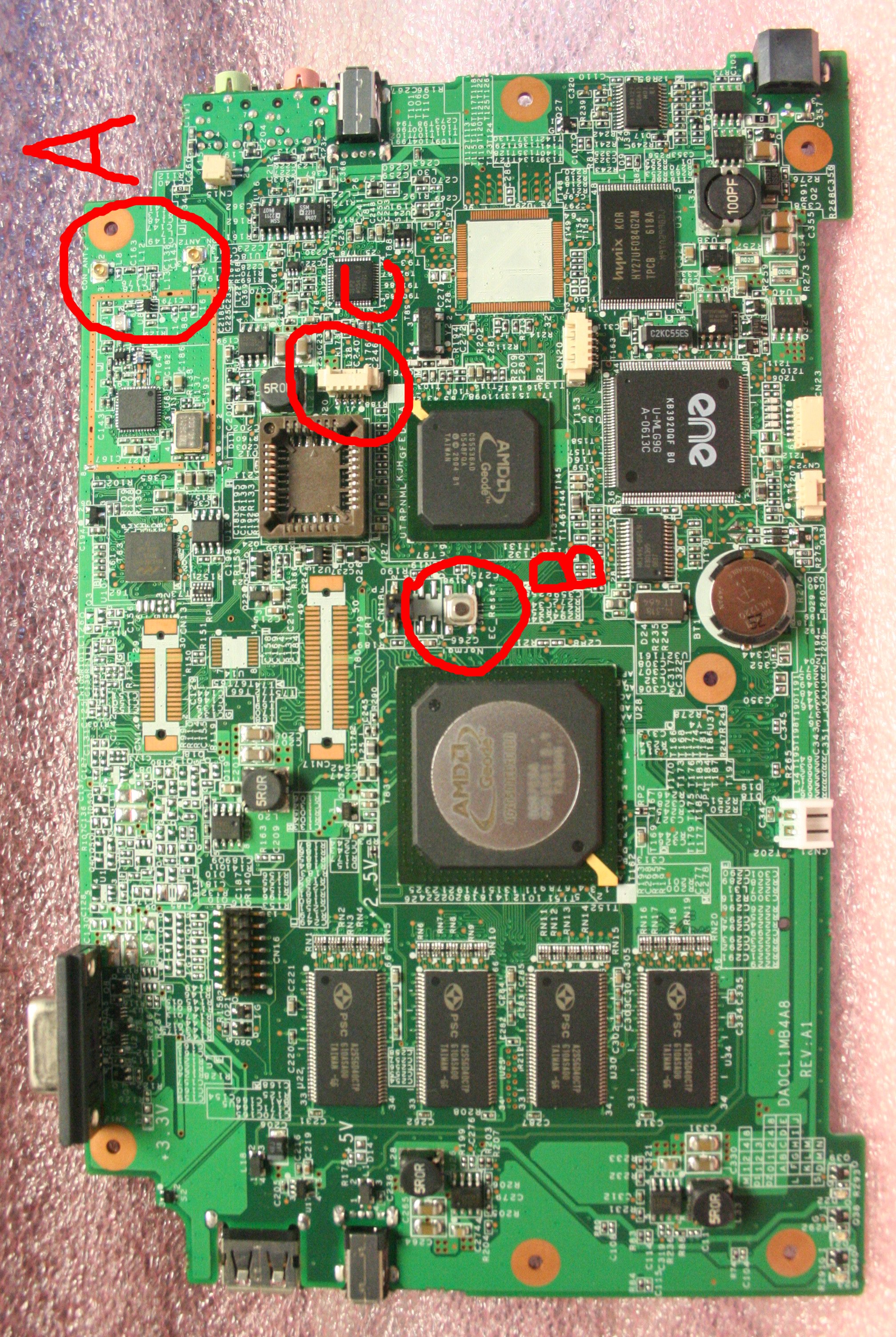
See A-test Developer Board for a close-up picture of the A-test PCB. In this photo, (A) refers to the wifi antenna connectors, (B) to the reset button, and (C) to the serial board connector.
This is very early hardware: it has not yet undergone extensive testing. It is not unusual with such boards that some component or another has a problem of some sort; sometimes this is only seen in a small fraction of samples.
So far, the hardware has been pretty solid. Please report suspected problems to the devel list. We've also created a Trac component (hardware) http://dev.laptop.org/newticket for tracking these problem reports, and please file them there as well.
Note that on these boards the wireless will not be "canned". This causes the noise floor to be extremely high, as the reciever is out in the open where anything can interfere; as a result, those boards are unsuitable for more than basic driver testing, as their range will be limited. B-Test boards should come through canned, but won't be available for some months. Boards now being shipped should arrive with antennae. If for some reason you need to find antennae for the connectors on the board (note there are two antennae connectors). There are several suppliers of antennae available though the gain is wrong. You can buy antennae with the right U.FL connectors through Netgate or Connex Wireless. Note that you should not attempt to use the wireless unless you have installed antennae due to some chance of overloading the transmitter, which may damage it.
Correct antennae have now been manufactured and boards should now arrive with antennae: those who have boards shipped from Brightstar without antennae the week of 6/11 should expect an envelope with antennae.
Handling of bare boards
Commercial hardware gets extensive testing for immunity to static damage, and the packaging provides more protection. With the developer boards, we have neither of these luxuries (yet). Testing sometimes uncovers design or component problems that end up requiring engineering changes, and the boards are bare, not protected by packaging. This ESD testing will occur later this summer, but the early developer boards have not seen such testing.
So please treat the boards carefully; boards are not yet common. Developer boards will start coming through with standoffs. They arrive in a anti-static (slightly conductive) bag, which you can leave the board on. Using boards on ESD protection stations is ideal. One can easily buy ESD plastic sheets for use on desktops. Certain carpets can generate static easily; please be even more careful on carpeting, particularly in dry climates. Similarly, there are anti-static sprays you can use on carpets to reduce their propensity to generate static.
The board plugged in is much more protected than when it is not. Touch nearby objects first to discharge any static. Touch one of the ground plane points on the board before touching other parts of the machine (e.g. the reset button). If you follow these guidelines, you are unlikely to have static related problems.
Types of Boards
- 30 Pre A-Test PCB, which have been built and distributed.
- 20 A-Test PCB's, which have been built and distributed
- 485 A-Test PCB's, which have been built and will be distributed through Brightstar. These can be distinguished from the first 50 boards in that they have real serial number bar codes on them.
Note that these boards lack DCON chips, and instead come with a standard VGA connector. We expect that production boards may ship with pads for VGA connectors, but no connector. Additionally, the Pre A-Test PCB have populated mini-pci connectors. The A-Test boards, these mini-pci connectors have been left off, but the pads are included and will probably be included on production boards. We want the same electronics to be as flexible as possible, so long as it does not increase cost of the units.
The A-Test PCB's include a socketed ROM chip for BIOS development, though this socket will not be on production boards. You will note these are empty; the BIOS is now stored in the serial flash chip that is interfaced via the embedded controller. Note that the process for updating the serial flash under Linux is not yet available and at the moment involves booting DOS and updating the flash chip using a utility from Quanta. Unless you are directly involved in BIOS development, you should stear clear of BIOS updates until/unless instructed by responsible people working on behalf of OLPC.
Insyde BIOS Notes
The Insyde BIOS should no longer be used as we now use LinuxBIOS. Insyde BIOS however, underwent minimal testing; our great thanks to Insyde for cooperating with the OLPC project and extremely generously donating several days of engineering to help bring up our boards, despite the lack of long term opportunity.
Note that the Insyde BIOS has expired; to use it at all, please set the date back to sometime in July 2006.
You should be Upgrading to LinuxBIOS.
There may be some problems with certain hardware in the Insyde BIOS that will not be present when running Linux; you may find it expedient to try other hardware that interacts better with the Insyde BIOS. This should in no way be thought of as a reflection of the Insyde BIOS quality, just that the usual amounts of testing and timing adjustment it would have undergone are *not* present in the BIOS image we are currently using. Please file bug reports to help others who may have similar problems.
To configure the flash memory interface in the Insyde BIOS, follow the following sequence.
Enter CMOS setup: (Press F1 during POST)
- C. Motherboard Device Configuration
- -> A. Drive Configuration
- -->Flash Configuration
- --->Flash Interface: Enabled
- --->Chip select 0 - size: 8K/16B
- --->Base: PCI default
- --->Type: NAND I/O
Note that LinuxBIOS, when we move to it, will always set the controller to bare flash.
To enable the UART with the Insyde BIOS, follow the following sequence.
Enter CMOS setup: (Press F1 during POST)
- C. Motherboard Device Configuration
- -> B. I/O Configuration
- -->UART Port A: 0x3F8 IRQ4
- -->UART Mode: Serial - 16550 compatible
Don't forget the save the configuration when you leave the setup.
Linux BIOS Status
Thanks for your patience! here are the instructions for Upgrading to LinuxBIOS (pt). Coincindentally, they get you going on a "thin" fedora version with Sugar, if you want (the installation of LinuxBIOS is done from the OLPC Fedora distribution, but that does not require you to use Fedora afterwards).
Power Starvation
The OLPC power supply is supposed to have (not yet verified by testing) enough power to power according to specifications, a single USB 2 port; it has three ports. So if you plug power hungry devices into the system, please make sure they are externally powered or interfaced via a powered hub. Conventional disk drives often draw too much power, particularly when being heavily used, and you can expect unreliable results. This is not uncommon in laptops; engineering for worst case power consumption adds expense.
pre-A Reset
In the pre-A boards, resetting the board is a bit of a challenge.
- Unplug the power supply from the board
- You will find a little button on the *bottom* of the board (non-component side), which you must press.
The regular "A-Test" boards have a hard reset button on the top.
Connectors / LEDs
- All remaining questions are in italics. Please remove the question if you answer it!
- Details should be correct for all pre-A and A-test boards.
- All of these numbers are allocated starting top left corner, allocated in scanline fashion.
- The front of the board is the side with the VGA connector and the Geode processor.
Warnings
- Just because it doesn't say it's changing, doesn't mean that it won't change!
- Do NOT confuse J1 with CN9! You will fry the audio!
- Do NOT populate both L36 and L37! (see CN23 PS/2 connector).
Back of board
| Code | Name | Description and Pinout |
|---|---|---|
| CN1 | JTAG Connector for Marvell wireless chip | Hirose FH12 0.5mm pitch 10 pin; 1=TRST 2=TDI 3=TMS 4=TCK 5=RTCK 6=TDO 7=RESET 8=GND 10=3.3v |
| CN2 | Old LCD Connector | Definition changing. |
| CN3 | External stereo audio line output (switched) | |
| CN4 | USB | |
| CN5 | External mono microphone connector (switched) | |
| CN6 | USB | |
| CN7 | USB | |
| CN8 | Mono right side speaker connector | (Pin 1: Right +, 2: Right -) |
| CN9 | Internal stereo speaker connector | (Pin 1: Left -, 2: Left +, 3: Right -, 4: Right +) |
| CN10 | No longer exists | (2-pin CN9 and CN10 were combined to 4-pin CN9) |
| CN11 | DC input jack | (10V-24V; nominal 12V) Center positive. |
| CON1 | Unused large solder pads | (was mini-PCI on pre-A-Test boards) |
| D2 | LED. | Definition changing. Same output as D22 (front/back view). |
| D3 | LED. | Definition changing. Same output as D21 (front/back view). |
| D4 | LED. | Definition changing. Same output as D23 (front/back view). |
Front of board
| Code | Name | Description and Pinout |
|---|---|---|
| CN12 | CRT for developer boards only | |
| CON_ANT1 | U.FL connector for left? antenna | confirm left? |
| CON_ANT2 | U.FL connector for right? antenna | confirm right? |
| CN13 | Wireless interface test points. | Definition changing. |
| CN14 | Used for DCON Debugging. | Definition changing. |
| CN15 | Internal microphone connector | (Pin 1: Gnd, 2: Audio) |
| CN16 | AMD Geode JTAG Connector | |
| CN17 | Used for DCON Debugging. | Definition changing. |
| J1 | Serial port connector. | 3.3V levels. (Pin 1: 3.3V Power, 2: TxD, 3: RxD, 4: Gnd) |
| CN18 | CRT/LCD Jumper | 1/3 = CRT, Removed = LCD |
| CN19 | Unused and unsoldered jumper. | |
| CN20 | Used for manufacturing | Serial Flash programming. Requires special fixture. |
| CN21 | Battery connector | (Pin 1: Gnd, 2: VBat). Battery is 5-cell NiMH, nominal ~6.0V. |
| CN22 | Battery sensor. | Definition changing. |
| CN23 | Internal PS/2 Connector to keyboard & input module |
(Pin 1: TP Data, 2: TP Clk, 3: Gnd, 4: KB Data, 5: KB Clk, 6: Power). Power is 5V if L36 populated, 3.3V if L37. L36/L37 located above pin 6. |
| D21 | LED. | Definition changing. Same output as D3 (front/back view). |
| D22 | LED. | Definition changing. Same output as D2 (front/back view). |
| D23 | LED. | Definition changing. Same output as D4 (front/back view). |
Software notes
Knoppix is known to "just work" when booting from CD; it does not correctly install onto disk (but then again, this is often true for the Knoppix CD).
Full Fedora Core 5 and Ubuntu Breezy releases have both been installed onto external USB disks and run; there are problems installing Linux you may want to be aware of. There are (at least) two reasons:
- the usual initrd does not currently include drivers for booting off of USB on either system.
- there is a delay at boot time before you can access an external USB disk. So if the system tries to boot before the hardware is ready, the expected chaos ensues. Right now, Linux doesn't seem to have a great way to wait until a USB device is fully ready.
Fedora notes
Fixes for the above problems are being pushed upstream into Fedora. More information on full Fedora and the OLPC Fedora distribution installation is available on the Software page. That page also contains information on how to get Fedora running on the boards on external USB storage.
Other Software observations
The JFFS2 file system is up on the flash. Please contact Dave Woodhouse before working on the driver itself as he is in the midst of heavy development.
Bug reporting
A bug tracking system has been established. If you suspect hardware trouble, please file a bug under product "OLPC Hardware", component "Pre A-Test" or "A-Test" as appropriate. To create a new ticket in the bug reporting system, go here. [1]. Note that we may require you to return the boards for failure analysis: this is very important to us, and your help here may be essential to detect serious issues that should be fixed. We are holding back spares to enable us to ship out replacement boards for failed boards, to keep developers able to work. Mark hard failures as severe bugs. Please include serial numbers in bug reports.
Similarly, we'll establish a component for the BIOS. Do not expect any problems with the Insyde BIOS to be fixed, though as a courtesy to Insyde, who have been very generous, and to other developers who may run into problems using it, please file bugs against the Insyde BIOS as well.
Protective Case Design
There are DXF files for building a protective case for the developer boards available here [2].