User:Jaffa225
I participated in G1G1 and am now happily hacking my XO. Thanks to JoshSeal, who sent me some of his power-plug samples, I am now trying to come up with useful renewable sources of power. So far, I've sent away for two non-amorphous 10W solar panels, and am happy to say they've arrived and are everything I'd hoped for! The site I bought them from, seemed a bit of a gamble, as the page was fraught with discrepancies. So now I have what appear to be two Suntech STP010-12/Kb 10 Watt polycrystalline panels. In case anyone would like to know where I got them, it was http://rvprotectionproducts.com/index.php?p=product&id=1611&parent=0.
If you check it out, be aware that the page should be taken with a grain of salt. They are 10W panels, at least in my case, and not 30W as the overview states. Also, it references the STA010-12 in one place, which appears to be a more recent model, but as said, I was sent STP010-12/Kb panels. Anyway, I think I was lucky and got exactly what I wanted. Also, everyone should be aware that I am adapting these panels to the XO myself, with the power-plugs samples that Josh was so nice to send me. Thanks again, Josh!
Here's an update for anyone who's interested. I needed to do more than adapt the output wires from the panels to the XO DC-plug. It turns out the the panel's output is sub-optimal for the XO. Their voltage is generally too high, especially when the amperage is at their peak, but I'm thankfully able to take advice from my brother, who's going to school for electrical engineering. He suggested I buy some (about 5) 5W, 13V zener diodes to regulate the voltage. I was only able to purchase one locally, so far, but the rest are on order so I should be able to get the results soon. I did do some preliminary testing out of curiosity with the one diode (by making sure the panels were putting out a voltage greater than 13V and a very tiny amperage) and got favorable results. I just hope that the idea of splitting the ~22W (short circuit power) among a few diodes works without blowing any out, due to actual diode rating differences within their tolerance. We'll see. --jaffa225 04:18, 17 October 2008 (UTC)
Okay, it's time for another update at last. I've actually done my experiments a while ago, but I can never seem to find the time to write it up. Anyway, yes, the five diodes did it! Burning them out would take prolonged optimal output from the panels, when the XO isn't drawing any power (or plugged in), I believe. Although in my testing of about a minute or two, unplugged, with full panel output didn't kill the diodes, they did get awfully hot. They even melted through the electrical tape I had them contained within. I don't really want to test it fully because then I'd have to replace the diodes. For some reason the XO squeals at certain power levels (getting higher-pitched, as power increases, until it stops squealing and seems normal). Once, I think, I even noticed the charging light shifting between red and green, while it was squealing. Hopefully that's not too bad for it, but so far, I've seen no other effects. I know it must have something to do with the charging (or battery drawing) circuitry, because when I take the battery out it stops the noise instantly. At about 600mA, I can take the battery out (with the backlight-LEDs turned off) and run fully on the panels! Also, I was pleasantly surprised to see the panels output 1.4A at one time, when the supposed maximum should be 1.14A! Even that, which I would guess was around 23V at the time (so ~32.2W!), didn't kill the zener diodes (but, as I said before, I didn't want to leave it long, in case they actually would)! Keep in mind that operating with the 13V zener diodes in place, at 1.4A, would only power the XO at about 18.2W, with lots (~14W) lost in the diodes. Most of the time the lighting is low, (at ~200-500mA) and the XO doesn't even register it as charging on the screen (with the picture of the lightning bolt on the battery). I hope that helps explain most things people would want to know. --jaffa225 05:52, 3 November 2008 (UTC)
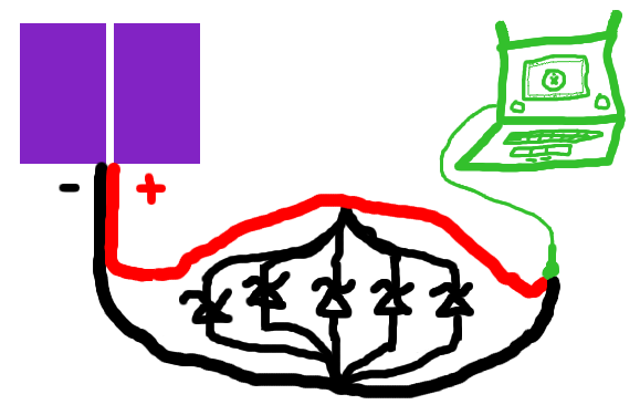
Here's a nice drawing of my Zener diodes in parallel to split the wattage, so as not to burn any out. Sure, the diodes don't have to connect directly to each other (just put them in parallel), but I wanted to reduce the amount of solder points in mine, and it's shown here. I didn't show it, but the panels are in parallel with each other too (like-colored wires tied together), and the fuse is in place, just in case. --jaffa225 07:06, 3 November 2008 (UTC)
