XSX Server Implementation
The implementation of an XSX School server is described on this page. You can also view the specification. The software running on this server is described in Trial1 Server Software.
Introduction
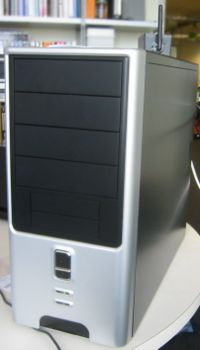
This is a server machine with a primary goal of supporting development of the School server/laptop software, including early trials. As this is a very limited production model (12-40 ?) and the design criteria are still undefined, flexibility wins out over cost. Off-the-shelf consumer PC hardware is being used.
Components
These are the particular components being used:
Motherboards
The mini-ITX form factor seemed to be the ideal in terms of meeting the requirements for relatively high processing power without a processor fan.
EPIA EN12000EG
The Via EPIA EN12000EG is based around Via's C7 processor, w. matching chip set.
Relevant features:
- 1.2 GHz VIA C7 (686) processor
- up to 1 GB DDR2 SDRAM
- 10/100/1000base-T (VIA VT6122)
- two SATA-1 ports (VIA VT6420)
- two UltraDMA-133 IDE ports (VIA VT82C686)
- four USB 2.0 ports (two off-board)
- one PCI slot
Documentation
- User's Manual (pdf) - includes jumper block descriptions
- Operating Guide (pdf)
EPIA CN10000EG
The Via EPIA CN10000EG is also based around Via's C7 processor, w. matching chip set.
Relevant features:
- 1.0 GHz VIA C7 (686) processor
- up to 1 GB DDR2
Documentation
- User's Guide (pdf) - includes jumper block descriptions
- Operating Guide (pdf)
Memory
The memory used in all motherboards is 1GB of 533 MHz (PC-4200) DDR2 SDRAM, in a 240 pin DIMM. The particular parts are:
- Kingston, KVR533D2N4/1G
- Corsair, VS1GSDS533D2
Disk Drives
- Seagate HDD
- Capacity ???
- Model ???
- Raid 0 ???
- Hitachi HDD
- Capacity ???
- Model ???
- Raid 0 ???
- Floppy
- N/A
Network Interfaces
Linksys
D-Link
Drivers
Ethernet
VIA Velocity
This is the driver for the 1000base-T interface on the EPIA EN10000EG motherboards.
Assembly Notes
Mechanical Assembly
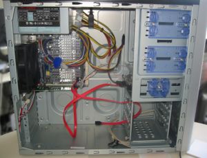
With the motherboard sitting on the conductive foam it is shipped in, insert the DIMM.
Swap out the back panel on the case to use the one included with the motherboard. From the outside of the case, push in on the bottom of the old one to remove. You will have to bend up the new shield over the ethernet and PS/2 mouse connectors. If using the EN10000 MB, punch out the holes for the video connectors. Test the shield on the MB BEFORE placing it in the case!
Attach the motherboard using the brass standoffs included with the case and four screws. Be careful not to "slide" the motherboard into place, you are likely to scrape components off the underside.
Remove the back panel piece blocking the first slot (normally AGP, but used for PCI on mini-ITX). Place the NIC into the PCI slot and screw the back flange down.
Cabling
The front panel switch cabling has to be rerouted up next to the mounts for 3.5 in. floppies in order to reach the MB.
Attach the MB power connector, and the front panel USB cables.
The system fan is currently left disconnected.
BIOS settings
Much more detail needed here. For now, assume that all defaults from the manufacturer are the same (not likely...)
Change the following BIOS settings:
- First boot should be from USB-CDROM, Second from USB-FDD, and third from HDD
- Change the SATA mode from RAID to IDE
- Halt on no errors
Component Tracking
In order to determine if problems are related to a particular supplier of a component, we must track the deployed components carefully. Here is the table where we store this information:
| Serial # | Motherboard | Memory | Disk | Net I/F | Case | Location |
|---|---|---|---|---|---|---|
| 001 | EN10000EG | Kingston | Seagate | LNE | AT | Cambridge |
| 002 | EN10000EG | Corvair | Seagate | - | - | Cambridge |
| 003 | EN10000EG | Corvair | Hitachi | LNE | AT | Cambridge |
Where for Network interface cards:
- LNE indicates the Linksys LNE100TX
- DFE indicates the D-Link DFE-530 TX
and for Cases:
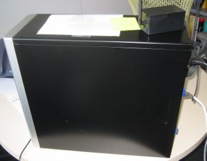
- AT indicates the Athenatech A602BS, using supplied power supply
- ?


