Making XO sensors/How to connect sensors: Difference between revisions
Jump to navigation
Jump to search
(content moved from Measure/Start) |
(section listing other sensor instructions using Special:PrefixIndex, Category:XO sensors) |
||
| Line 1: | Line 1: | ||
'''This details steps to build a low cost probe for connecting sensors to the XO for use in [[Measure]] and other activities that can read sensor input.''' |
'''This details steps to build a low cost probe for connecting sensors to the XO for use in [[Measure]] and other activities that can read sensor input.''' |
||
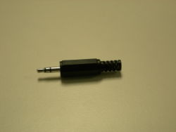
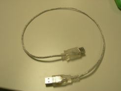
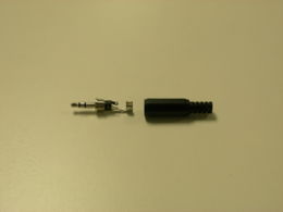
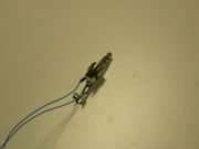
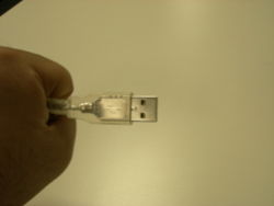
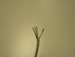
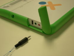
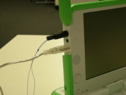
In general, you wire the sensor to a 3.5mm audio jack, and also to a USB connector if it requires voltage. |
|||
{| |
{| |
||
| Line 42: | Line 44: | ||
# The "Gnd" terminal (the Gnd of audio connector is connected to Gnd of USB connector" |
# The "Gnd" terminal (the Gnd of audio connector is connected to Gnd of USB connector" |
||
''' |
''' |
||
== Other sensor instructions == |
|||
Other pages describe how to build specific kinds of sensors. |
|||
{{Special:PrefixIndex/Making_XO_sensors/}} |
|||
[[Category:XO sensors]] |
|||
Latest revision as of 22:39, 7 July 2009
This details steps to build a low cost probe for connecting sensors to the XO for use in Measure and other activities that can read sensor input.
In general, you wire the sensor to a 3.5mm audio jack, and also to a USB connector if it requires voltage.
To summarize, do remember that we have identified three terminals
- The "Vin" terminal
- The "+ve" terminal
- The "Gnd" terminal (the Gnd of audio connector is connected to Gnd of USB connector"
Other sensor instructions
Other pages describe how to build specific kinds of sensors.
- Making XO sensors/Construir Sensor Luz
- Making XO sensors/How to connect sensors
- Making XO sensors/Lichtsensor
- Making XO sensors/Making a Humidity Sensor
- Making XO sensors/Making a Light Sensor
- Making XO sensors/Making a Magnetic Sensor
- Making XO sensors/Making a Switch Sensor
- Making XO sensors/Making a Temperature Sensor
- Making XO sensors/Making a Thermistor
