Making XO sensors/Making a Switch Sensor: Difference between revisions
Jump to navigation
Jump to search
m (Making a Switch Sensor moved to Making XO sensors/Making a Switch Sensor: support TOC of subpages) |
CallaUrrea (talk | contribs) No edit summary |
||
| Line 1: | Line 1: | ||
<center> |
<center> |
||
[[Image: |
[[Image:Switch 01.jpg||400px]] |
||
</center> |
</center> |
||
| Line 6: | Line 6: | ||
<center> |
<center> |
||
[[Image: |
[[Image:Switch 02.jpg|400px]] |
||
</center> |
</center> |
||
| Line 14: | Line 14: | ||
<center> |
<center> |
||
[[Image: |
[[Image:Switch 03.JPG|400px]] |
||
</center> |
</center> |
||
| Line 20: | Line 20: | ||
<center> |
<center> |
||
[[Image: |
[[Image:Switch 04.JPG|400px]] |
||
</center> |
</center> |
||
Revision as of 17:08, 16 October 2009
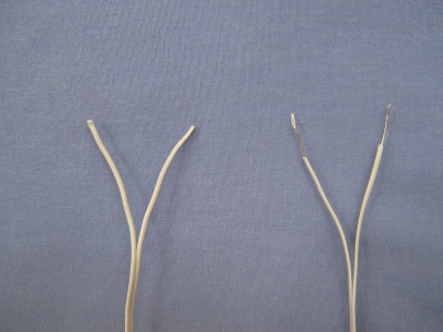
- As shown in the picture, tear the two ends of the wire apart and use a Stripper to strip the wire bare.
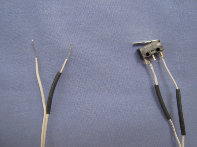
- Slide on the X (heat-compressible rubber tubing) onto both ends of the wire as shown.
Only one side is shown in the picture, but follow the same process for the other wire.
- Slide on the X (heat-compressible rubber tubing) onto both ends of the wire as shown.
- Next, use the soldering iron to connect the two ends of the wire to the switch.
This can be done by adding some solder to the two side contact points of the switch and to the bare ends of the wire.
Subsequently, join the two together as shown in the picture, and allow the solder to cool, solidify and thus connect.
- Next, use the soldering iron to connect the two ends of the wire to the switch.
- Next, slide the rubber tubing up the wire so that it completely covers the two contact points,
and then use X (hot air) to compress the rubber tubing onto the wire.
- Next, slide the rubber tubing up the wire so that it completely covers the two contact points,
- Completed Switch Sensor!
Other sensor instructions
- Making XO sensors/Construir Sensor Luz
- Making XO sensors/How to connect sensors
- Making XO sensors/Lichtsensor
- Making XO sensors/Making a Humidity Sensor
- Making XO sensors/Making a Light Sensor
- Making XO sensors/Making a Magnetic Sensor
- Making XO sensors/Making a Switch Sensor
- Making XO sensors/Making a Temperature Sensor
- Making XO sensors/Making a Thermistor


