Disassembly top: Difference between revisions
mNo edit summary |
|||
| (34 intermediate revisions by 14 users not shown) | |||
| Line 1: | Line 1: | ||
{{Translations}} |
|||
{{TOCright}} |
{{TOCright}} |
||
This is how to disassemble the top portion of an [[Hardware|XO laptop]]. This is part of the [[Disassembly]] section of the [[XO_Troubleshooting_Guide|Troubleshooting Guide]] and [[Repair|Repair Manual]]. |
|||
You might do a partial top disassembly: |
|||
* to tighten the hinge screws, |
|||
* to replace the screen or backlight, |
|||
* to inspect the touchscreen cable on an XO-4, |
|||
* to replace the bumpers, antennas, or panel plastics. |
|||
You might do a full top disassembly: |
|||
* to check or replace the [[Fix_clock|clock battery]], |
|||
* to attach a [[serial adapter]] for firmware or software diagnosis, |
|||
* to inspect and fully dry a motherboard after accidental immersion, |
|||
* to perform an [[SPI FLASH Recovery]], |
|||
* to investigate a heat spreader temperature rise test failure on an [[XO-1.5]], |
|||
* to replace or upgrade the microSD card on an [[XO-1.5]], |
|||
* to replace or upgrade the wireless card on an [[XO-1.5]], [[XO-1.75]], or [[XO-4]], |
|||
* to check for twists and breaks in the antenna cables after [[antenna testing]], |
|||
* to release an SD card captured by the slot or a physical security device, |
|||
* to diagnose or repair components on the motherboard, |
|||
* to inspect or replace the motherboard, |
|||
== Similar Guides == |
|||
These other guides refer to disassembly of the laptop to reach a particular component: |
|||
* [[Antenna_replacement|Disassembling to replace an antenna]], ([[Disassembly_B4_wireless_antenna|B4 preproduction version]]) |
|||
* [[Disassembly_backlight|Disassembling the display to replace the backlight]] |
|||
* [[Disassembly_XO_person|Disassembling to replace the XO icon on the back cover]] |
|||
* [[Disassembly_bottom|Disassembling the bottom]] |
|||
== Video walkthroughs == |
|||
These instructions are also available in [http://dotsub.com/films/xotopdisassembly/index.php?autostart=true&language_setting=en_4762 video format] with English subtitles, courtesy of [[ILXO]]. |
|||
[[OLPC Australia]] maintain a set of [http://edu.laptop.org.au/help-videos Help Videos]. |
|||
== PDF walkthrough == |
|||
[[media:XO_Disasembly_(Top).pdf | XO 1.5 Disassembly Top (33-page PDF, 4.7MB)]] |
|||
== XO before disassembly == |
== XO before disassembly == |
||
As a precaution, remember to remove the battery. |
|||
[[image:screen_0.jpg|thumb|left|Before we begin]] |
|||
[[image:screen_0.jpg|thumb|left|Before we begin]] [[image:Keyboardstep1a.jpg|thumb|left|Remove the battery.]] |
|||
<br style="clear:both" /> |
<br style="clear:both" /> |
||
| Line 17: | Line 59: | ||
=== Step 2 === |
=== Step 2 === |
||
Open the antennas. Slide the two green panels up toward the USB ports, then lift them off to the side. |
|||
[[image:Screen_2a.jpg|thumb|left]] [[image:Screen_2b.jpg|thumb|left|Slide up]] [[image:Screen_2c.jpg|thumb|left|Lift off]] |
[[image:Screen_2a.jpg|thumb|left]] [[image:Screen_2b.jpg|thumb|left|Slide up]] [[image:Screen_2c.jpg|thumb|left|Lift off to the side]] |
||
<br style="clear:both" /> |
<br style="clear:both" /> |
||
| Line 28: | Line 70: | ||
[[image:Screen_3a.jpg|thumb|left]] [[image:Screen_3b.jpg|thumb|left]] |
[[image:Screen_3a.jpg|thumb|left]] [[image:Screen_3b.jpg|thumb|left]] |
||
<br style="clear:both" /> |
<br style="clear:both" /> |
||
Note that the game pad is now free to fall out -- be careful not to lose it! |
|||
'''Caution:''' on the XO-4 touch, be careful not to rip the ribbon at the base of the front panel that connects the touch bezel to the motherboard. |
|||
Pull the bottom just enough to pull out the top of the panel, fold down, and disconnect the ribbon at the bottom. |
|||
== Removing the screen == |
== Removing the screen == |
||
Note that if the screen and motherboard aren't being changed, it is not necessary to actually disconnect the screen in order to access the motherboard. Follow step 1, then gently move the screen to perform the rest of the steps (to remove the back cover). |
|||
=== Step 1 === |
=== Step 1 === |
||
| Line 43: | Line 92: | ||
[[image:Screen_4b.jpg|thumb|left|Slide out gently]] [[image:Screen_4c.jpg|thumb|left]][[image:Screen_4d.jpg|thumb|left| Watch out for cables!]] |
[[image:Screen_4b.jpg|thumb|left|Slide out gently]] [[image:Screen_4c.jpg|thumb|left]][[image:Screen_4d.jpg|thumb|left| Watch out for cables!]] |
||
<br style="clear:both" /> |
<br style="clear:both" /> |
||
If you are just accessing the motherboard, and not replacing it or the display, do not unplug the display cables. Simply move the display slightly to access the back cover screws behind it. With every connect/disconnect cycle, there is a chance of damage to the display cable connectors on the motherboard. If you decide not to disconnect the screen, then after removing the back cover screws (which are behind the screen) the screen should be reattached with at least two screws in order to prevent damage to its cables or the connectors while moving the laptop. |
|||
The cable connectors have a black plastic bar holding the cable down. To unclamp the cable you have to lift that bar by tugging on the little tab away from the circuit board. |
|||
[[image:Screen_4e.jpg|thumb|left| Unhook the cable]] [[image:Screen_4f.jpg|thumb|left| Watch out for this little cable, too.]] [[image:Screen_4g.jpg|thumb|left| Good to go!]] |
[[image:Screen_4e.jpg|thumb|left| Unhook the cable]] [[image:Screen_4f.jpg|thumb|left| Watch out for this little cable, too.]] [[image:Screen_4g.jpg|thumb|left| Good to go!]] |
||
<br style="clear:both" /> |
|||
== Optional: Removing the backlight == |
|||
'''You do not have to remove the backlight if you are trying to get to any other part.''' |
|||
=== Step 1 === |
|||
Remove tape from backlight connection cable to expose the back of the display. |
|||
[[image:backlight1a.JPG|thumb|left|Peel off tape]] [[image:backlight1b.JPG|thumb|left|Remember tape on the sides, too!]] |
|||
<br style="clear:both" /> |
|||
=== Step 2 === |
|||
Disconnect the backlight from the display by removing the two screws shown below using a #0 Philips head screwdriver. |
|||
[[image:backlight1c.JPG|thumb|left|Take out two screws where indicated]] [[image:backlight1d.JPG|thumb|left|Lift the backlight up and out.]] [[image:backlight1e.JPG|thumb|left|Separated backlight]] |
|||
<br style="clear:both" /> |
|||
== Optional: Removing the wireless antenna == |
|||
'''You do not need to remove the wireless antenna if you are trying to get to any other part.''' |
|||
=== Step 1 === |
|||
Keep the screen out of the way until the replacement is complete. |
|||
[[image:antenna1a.JPG|thumb|left|Take out 4 screws]] [[image:antenna1b.JPG|thumb|left|Turn over. Pull up and remove the back plate]] |
|||
<br style="clear:both" /> |
|||
[[image:Antenna1c.JPG|thumb|left|Take out two screws holding the top bar in place]] [[image:Antenna1d.JPG|thumb|left|Watch out for this tab! Pop it out on both sides]] [[image:Antenna1e.JPG|thumb|left|Pull the top bar off.]] |
|||
<br style="clear:both" /> |
|||
=== Step 2 === |
|||
[[image:antenna2a.JPG|thumb|left|Unclip the cable as shown]] [[image:antenna2b.JPG|thumb|left|Peel up the tape.]] |
|||
[[image:Antenna2c.JPG|thumb|left|Remove the two screws.]] |
|||
<br style="clear:both" /> |
|||
[[image:Antenna2d.JPG|thumb|left|Watch out for this tab!]] [[image:Antenna2e.JPG|thumb|left|Carefully pull out the antenna.]] [[image:Antenna2f.JPG|thumb|left|A removed antenna.]] |
|||
<br style="clear:both" /> |
<br style="clear:both" /> |
||
| Line 83: | Line 101: | ||
=== Step 1 === |
=== Step 1 === |
||
[[image:antenna1a.JPG|thumb|left|Take out 4 screws]] [[image:antenna1b.JPG|thumb|left|Turn over. |
[[image:antenna1a.JPG|thumb|left|Take out 4 screws]] [[image:antenna1b.JPG|thumb|left|Turn over. Lift the back cover slightly near the handle, then slide it towards the handle by about 2mm, then remove.]] |
||
<br style="clear:both" /> |
|||
== Optional: Removing the "XO Person" on the back cover == |
|||
'''You do not need to remove the "XO Person" on the back cover if you want to get to any other part.''' |
|||
=== Step 1 === |
|||
[[image:Xoman1.JPG|thumb|left|Turn the back plate over. Note where the colored plastic fits in.]] [[image:Xoman2.JPG|thumb|left|Use a screwdriver to pop these out]] |
|||
<br style="clear:both" /> |
|||
[[image:Xoman3.JPG|thumb|left|Turn plate over so the XO man faces you. Pull the plastic part out.]] [[image:Xoman4.JPG|thumb|left|Note how the tabs fit in with the back plate.]] |
|||
<br style="clear:both" /> |
|||
== Replacing the "XO Person" on the back cover == |
|||
=== Step 1 === |
|||
[[image:Xoman5.JPG|thumb|left|Fit the new piece in the back plate and snap it back in place.]] |
|||
<br style="clear:both" /> |
<br style="clear:both" /> |
||
| Line 108: | Line 109: | ||
[[image:Antenna3e.JPG|thumb|left|Turn over. Replace the back plate.]] [[image:Antenna3fi.JPG|thumb|left|Pick the right screw!]] [[image:Antenna3fii.JPG|thumb|left|Turn over. Secure the back plate by putting in the four screws where indicated.]] |
[[image:Antenna3e.JPG|thumb|left|Turn over. Replace the back plate.]] [[image:Antenna3fi.JPG|thumb|left|Pick the right screw!]] [[image:Antenna3fii.JPG|thumb|left|Turn over. Secure the back plate by putting in the four screws where indicated.]] |
||
<br style="clear:both" /> |
<br style="clear:both" /> |
||
== Replacing the wireless antenna == |
|||
=== Step 1 === |
|||
[[image:Antenna3a.JPG|thumb|left|Carefully put in the new wireless antenna]] [[image:Antenna3bi.JPG|thumb|left|Pick the right screw!]] [[image:Antenna3bii.JPG|thumb|left|Screw in the antenna]] |
|||
<br style="clear:both" /> |
|||
=== Step 2 === |
|||
[[image:Antenna3c.JPG|thumb|left|Clip the antenna cable back in.]] [[image:Antenna3d.JPG|thumb|left|Replace the top bar. Do not forget the tabs on the sides! Replace the screws to secure the bar.]] |
|||
<br style="clear:both" /> |
|||
[[image:Antenna3e.JPG|thumb|left|Turn over. Replace the back plate.]] [[image:Antenna3fi.JPG|thumb|left|Pick the right screw!]] [[image:Antenna3fii.JPG|thumb|left|Turn over. Secure the back plate by putting in the four screws where indicated.]] |
|||
<br style="clear:both" /> |
|||
== Replacing the backlight == |
|||
Replace the backlight by attaching the new backlight to the display. Ensure the backlight connection cable is attached and lying flat along the display. |
|||
[[image:backlight2a.JPG|thumb|left|Gently put the new backlight in place]] [[image:backlight2b.jpg|thumb|left|Reattach tape to the center of the backlight]] |
|||
<br style="clear:both" /> |
|||
[[image:backlight2c.JPG|thumb|left|Place the two screws back in]] [[image:backlight2d.JPG|thumb|left|Reattach the tape on the small cables]] |
|||
<br style="clear:both" /> |
|||
== Replacing the screen == |
== Replacing the screen == |
||
| Line 139: | Line 120: | ||
[[image:Screen_5c.jpg|thumb|left| Gently slide screen back in]] [[image:Screen_5d.jpg|thumb|left| The screws with the large heads (4) go back in]] |
[[image:Screen_5c.jpg|thumb|left| Gently slide screen back in]] [[image:Screen_5d.jpg|thumb|left| The screws with the large heads (4) go back in]] |
||
<br style="clear:both" /> |
<br style="clear:both" /> |
||
== Replacing the camera == |
|||
* Access the motherboard by removing the back (removing the LCD and the microphone cable from the motherboard in the process of removing the back.) |
|||
* Remove the speaker cables, the keyboard cable, and the battery cables. |
|||
* Disconnect the antenna cables to the WLAN module. (XO-1.5 and later: remove the WLAN module.) |
|||
* There are three screws holding the heat spreader down (1.5 and later have 4 screws). Remove them. |
|||
* You should now be able to lift the motherboard out, starting with the side with two USB ports. |
|||
* Remove the camera and camera mount as one unit. (Be careful not to damage the motherboard when removing the camera mount. It is adhered to the USB connector with double sided tape. Remove the camera and its mount first, then disconnect the cable. When mounting, make the electrical connection before placing the camera and mount into position.) |
|||
* When reinserting the motherboard, make sure all cables are clear and insert the side with the audio/power jacks first. |
|||
== Replacing the front panel == |
== Replacing the front panel == |
||
| Line 144: | Line 136: | ||
=== Step 1 === |
=== Step 1 === |
||
Slide the front panel |
Slide the front panel out for these hooks [[image:Screen_6b.jpg|thumb|left| The rest of the panel slides into place]] |
||
[[image:Screen_6a.jpg|thumb|left| Watch out for these hooks]] [[image:Screen_6b.jpg|thumb|left| The rest of the panel slides into place]] |
|||
<br style="clear:both" /> |
<br style="clear:both" /> |
||
| Line 159: | Line 149: | ||
[[Category:Repair]] |
[[Category:Repair]] |
||
[[Category:Hardware]] |
|||
[[Category:Pictures]] |
|||
Latest revision as of 21:51, 8 January 2014
This is how to disassemble the top portion of an XO laptop. This is part of the Disassembly section of the Troubleshooting Guide and Repair Manual.
You might do a partial top disassembly:
- to tighten the hinge screws,
- to replace the screen or backlight,
- to inspect the touchscreen cable on an XO-4,
- to replace the bumpers, antennas, or panel plastics.
You might do a full top disassembly:
- to check or replace the clock battery,
- to attach a serial adapter for firmware or software diagnosis,
- to inspect and fully dry a motherboard after accidental immersion,
- to perform an SPI FLASH Recovery,
- to investigate a heat spreader temperature rise test failure on an XO-1.5,
- to replace or upgrade the microSD card on an XO-1.5,
- to replace or upgrade the wireless card on an XO-1.5, XO-1.75, or XO-4,
- to check for twists and breaks in the antenna cables after antenna testing,
- to release an SD card captured by the slot or a physical security device,
- to diagnose or repair components on the motherboard,
- to inspect or replace the motherboard,
Similar Guides
These other guides refer to disassembly of the laptop to reach a particular component:
- Disassembling to replace an antenna, (B4 preproduction version)
- Disassembling the display to replace the backlight
- Disassembling to replace the XO icon on the back cover
- Disassembling the bottom
Video walkthroughs
These instructions are also available in video format with English subtitles, courtesy of ILXO.
OLPC Australia maintain a set of Help Videos.
PDF walkthrough
XO 1.5 Disassembly Top (33-page PDF, 4.7MB)
XO before disassembly
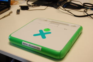
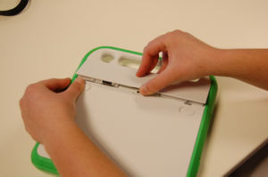
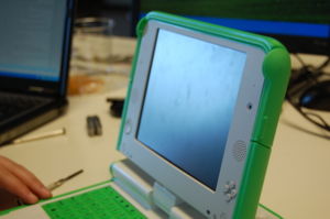
As a precaution, remember to remove the battery.
Removing the front panel
Step 1
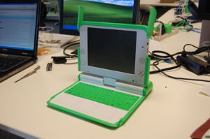
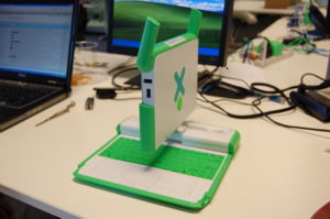
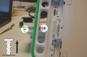
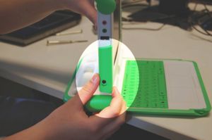
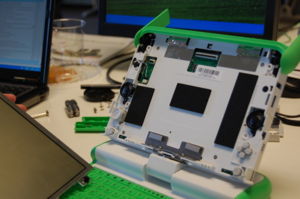
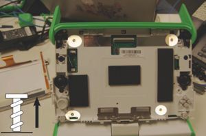
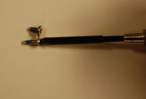
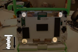
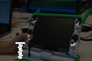
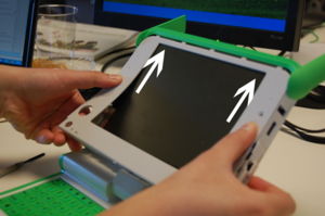
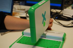
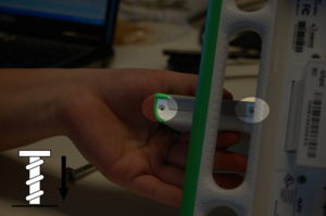
Open the laptop and flip the screen up. Rotate it a 90 degree angle as shown in the sequence below. Next, remove the screws from the bottom of the screen - there are two on each side (right/left) of the XO, so make sure to get all four.
Step 2
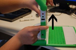
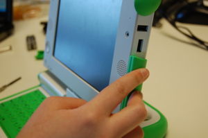
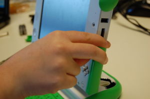
Open the antennas. Slide the two green panels up toward the USB ports, then lift them off to the side.
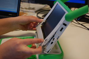
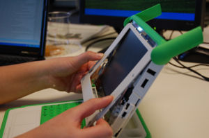
Step 3
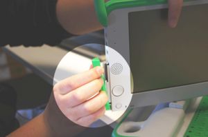
Finally, pull off the front panel. It is tabbed, so it can simply be pulled out. Pull the bottom out (where the screws came out), and gently slide the piece downwards and out.
Note that the game pad is now free to fall out -- be careful not to lose it!
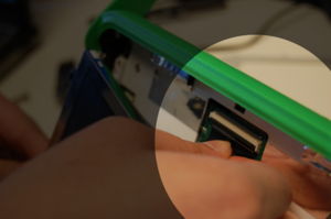
Caution: on the XO-4 touch, be careful not to rip the ribbon at the base of the front panel that connects the touch bezel to the motherboard. Pull the bottom just enough to pull out the top of the panel, fold down, and disconnect the ribbon at the bottom.
Removing the screen
Note that if the screen and motherboard aren't being changed, it is not necessary to actually disconnect the screen in order to access the motherboard. Follow step 1, then gently move the screen to perform the rest of the steps (to remove the back cover).
Step 1
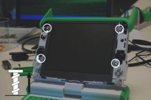
To get the screen out, remove the four screws highlighted.
Step 2
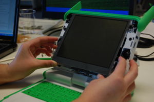
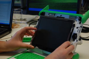
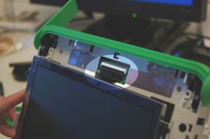
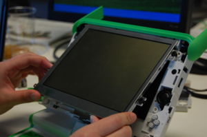
Next, carefully slide the screen out, pulling the bottom out. Do not tug it or let go, as it will still be connected to the motherboard by two cables.
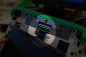
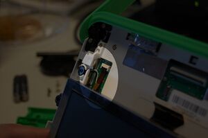
If you are just accessing the motherboard, and not replacing it or the display, do not unplug the display cables. Simply move the display slightly to access the back cover screws behind it. With every connect/disconnect cycle, there is a chance of damage to the display cable connectors on the motherboard. If you decide not to disconnect the screen, then after removing the back cover screws (which are behind the screen) the screen should be reattached with at least two screws in order to prevent damage to its cables or the connectors while moving the laptop.
The cable connectors have a black plastic bar holding the cable down. To unclamp the cable you have to lift that bar by tugging on the little tab away from the circuit board.
Removing the back cover / reaching the motherboard
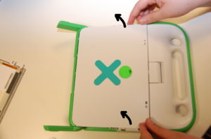
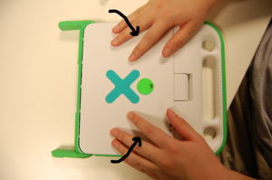
Step 1
Replacing the back cover
Step 1
Replacing the screen
Step 1
Reattach the screen by sliding the connection cables into place and clipping them back down (it is generally easier to clip the thinner one that has a longer tether first). Reseat the screen, making sure that it sits flat and that none of the spacers are gone.
Replacing the camera
- Access the motherboard by removing the back (removing the LCD and the microphone cable from the motherboard in the process of removing the back.)
- Remove the speaker cables, the keyboard cable, and the battery cables.
- Disconnect the antenna cables to the WLAN module. (XO-1.5 and later: remove the WLAN module.)
- There are three screws holding the heat spreader down (1.5 and later have 4 screws). Remove them.
- You should now be able to lift the motherboard out, starting with the side with two USB ports.
- Remove the camera and camera mount as one unit. (Be careful not to damage the motherboard when removing the camera mount. It is adhered to the USB connector with double sided tape. Remove the camera and its mount first, then disconnect the cable. When mounting, make the electrical connection before placing the camera and mount into position.)
- When reinserting the motherboard, make sure all cables are clear and insert the side with the audio/power jacks first.
Replacing the front panel
Step 1
Slide the front panel out for these hooks
Step 2
Slide the green side pieces back into place. Then, rotate the XO 90 degrees and put the remaining screws back. Don't forget that the screws go in on both sides (right/left).
