802.11s Connectivity Test Plan: Difference between revisions
No edit summary |
|||
| (8 intermediate revisions by 5 users not shown) | |||
| Line 1: | Line 1: | ||
{{Translations}} |
|||
==Test plan for the OLPC 802.11s implementation== |
==Test plan for the OLPC 802.11s implementation== |
||
This is a first attempt to systematically describe testing procedures for the Marvell/OLPC 802.11s implementation on the XO laptop. |
This is a first attempt to systematically describe testing procedures for the Marvell/OLPC 802.11s implementation on the XO laptop. |
||
[Note: |
[Note: This document is based mostly on tests that have been already performed by many people in different environments. ] |
||
| ⚫ | |||
The main concept behind our implementation is that of functional splitting of the networking stack between the WiFi radio and the Host CPU. The ARM processor driving the 88W8388 radio processes Layer-2 frames, while the Host CPU processes packets (IP or any other Layer-3 protocol). |
The main concept behind our implementation is that of functional splitting of the networking stack between the WiFi radio and the Host CPU. The ARM processor driving the 88W8388 radio processes Layer-2 frames, while the Host CPU processes packets (IP or any other Layer-3 protocol). |
||
| ⚫ | |||
This architecture allows for power savings (since only the Marvell SoC radio is necessary for frame forwarding) and flexibility with upper layer protocols (since it is not depending on any specific Layer-3 protocol - automatically supporting IPv6 for example). |
This architecture allows for power savings (since only the Marvell SoC radio is necessary for frame forwarding) and flexibility with upper layer protocols (since it is not depending on any specific Layer-3 protocol - automatically supporting IPv6 for example). |
||
| Line 28: | Line 27: | ||
[[image:802.11s_2.jpg|center]] |
[[image:802.11s_2.jpg|300px|center]] |
||
| Line 47: | Line 46: | ||
[[image:802.11s_3.jpg|center]] |
[[image:802.11s_3.jpg|300px|center]] |
||
| Line 59: | Line 58: | ||
[[image:802.11s_4.jpg|center]] |
[[image:802.11s_4.jpg|300px|center]] |
||
| Line 67: | Line 66: | ||
[[image:802.11s_5.jpg|center]] |
[[image:802.11s_5.jpg|300px|center]] |
||
| Line 82: | Line 81: | ||
[[Image:802.11s_Connectivity_Test_Plan.doc]] - Original document |
[[Image:802.11s_Connectivity_Test_Plan.doc]] - Original document |
||
==Test cases from Marvell for the OLPC XOs == |
==Test cases from Marvell for the OLPC XOs == |
||
* Driver / Firmware version |
|||
ethtool -i eth0 |
ethtool -i eth0 |
||
* Start one OLPC mesh node (node A) with fixed SSID, check beacon for SSID |
|||
* Start second OLPC mesh node (node B) with same SSID, and check if it assumes the BSSID of node A. This can be checked from the beacon. |
|||
* Give a fixed IP address to Node A and Node B. Then ping node B from Node A. Check if ARP packets are sent by Node A. Check if ARP table is populated with the IP and MAC address of Node B. Check if the ICMP packets are sent correctly. Check if the ICMP replies are received. |
|||
* Clear the ARP table of node B. Node ping Node A from Node B. Check if the ARP packets are send from Node B. Check if the ARP table is populated with the IP and MAC address of Node A. Check if the ICMP packets are sent correctly. Check if the ICMP replies are received. |
|||
* Start third OLPC mesh node (node C) with same SSID, and check if it assumes the BSSID of node A. This can be checked from the beacon. |
|||
* Repeat steps 4 & 5 but replace Node B with Node C. |
|||
* Repeat steps 4 & 5 but replace Node A with Node C. |
|||
* Start 2 more OLPC nodes to have 5 OLPC nodes. Check if each node transmits a beacon with the same BSSID and SSID of node A. |
|||
* Start a ping from each node to any other random node. Check if the pings are properly received. |
|||
* Form the machines as each point in a pentagon. Send a ping from one end of the pentagon to the other end. Check if the pings are going through the correct route. Check the RREPs. Check the return RREQ. Check the correct final path. |
|||
* Look at the forwarding table to see how many routes are formed to go from one end node to the other. |
|||
* Mesh TTL and Mesh E2E Sequence Number should be seen in the Ping Request /Reply packets. |
|||
E2E sequence number -> offset 33 in the packet (2 bytes long) |
|||
TTL -> offset 35 in the packet (1 byte long) |
|||
* Observe the route taken by the Ping Request and the Ping Response frames. Disconnect one node from the route and make sure that the route is re-established and the ping still goes through |
|||
* Run an iperf test on this linear network and observe the through over a 4-hop network. |
|||
* Run through the above steps 15 and 16 with a different network configuration where, on every node, you would blind all the nodes from each other except for the neighbor nodes. If you disconnect one of the neighbor nodes network (basically disable the wireless or just switch off the laptop), you should see that the ping should fail. Deleting any one of the other neighbor nodes from the blinding table should help pings go through fine again because a new route will be formed. |
|||
* LED-GPIO connections |
|||
WLAN_ENLED (LED 1) -> GPIO01 ->this GPIO should be used for showing that there is association or not. |
WLAN_ENLED (LED 1) -> GPIO01 ->this GPIO should be used for showing that there is association or not. |
||
WLAN_ACTLED (LED 2) -> GPIO12 -> this GPIO should be used for showing that there is any traffic or not. |
WLAN_ACTLED (LED 2) -> GPIO12 -> this GPIO should be used for showing that there is any traffic or not. |
||
* Configure four MPs (MP1,MP2,MP3 and MP4) |
|||
Ensure each node can ping any random node. Configure MP2 to be the MPP and associate it to a Netgear AP(this MPP should have a eth0 as well as a msh0 interface ip).Ensure that MP2 can ping the AP as well as ping all the internal nodes. Run the mpp.py script on the MPP and the mppreq_client script on the MP. Check for the MPP request frame from the MP on the MPP. Now ping the Netgear AP from the MP and check whether the ping goes through. |
Ensure each node can ping any random node. Configure MP2 to be the MPP and associate it to a Netgear AP(this MPP should have a eth0 as well as a msh0 interface ip).Ensure that MP2 can ping the AP as well as ping all the internal nodes. Run the mpp.py script on the MPP and the mppreq_client script on the MP. Check for the MPP request frame from the MP on the MPP. Now ping the Netgear AP from the MP and check whether the ping goes through. |
||
* Configure two MPPs and have an MP to associate to it. Ping the MPP from the MP. Now turn off one of the MPP and ensure that the MP associates to the other active MPP |
|||
* Validated the lsmesh utility |
|||
Utility displays all the neighboring nodes connected in the network. |
|||
* Configure four MPs (MP1, MP2, MP3 and MP4).Ensure each node can ping any random node. Run pings from any random node to the other and leave it running overnight. Run in open air - not shield room |
|||
* Configure four MPs (MP1, MP2, MP3 and MP4) |
|||
Ensure each node can ping any random node. Configure MP2 to be the MPP and associate it to a Netgear AP (this MPP should have a eth0 as well as a msh0 interface IP).Ensure that MP2 can ping the AP as well as ping all the internal nodes. Run the mpp.py script on the MPP and the mppreq_client script on the MP. Check for the MPP request frame from the MP on the MPP. Now ping the Netgear AP from the MP and check whether the ping goes through. Run this test overnight. |
Ensure each node can ping any random node. Configure MP2 to be the MPP and associate it to a Netgear AP (this MPP should have a eth0 as well as a msh0 interface IP).Ensure that MP2 can ping the AP as well as ping all the internal nodes. Run the mpp.py script on the MPP and the mppreq_client script on the MP. Check for the MPP request frame from the MP on the MPP. Now ping the Netgear AP from the MP and check whether the ping goes through. Run this test overnight. |
||
The MPP IP address in both the scripts should be: |
|||
** The same |
|||
** On the same subnet as the mesh network |
|||
** Should be different from the IP address of any other MP or MPP in the mesh subnet. |
|||
| ⚫ | * Introduce another MPP in the network. Then stop and start all the MPs again. Some MPs should use one MPP and some other should use the other MPP. It is assumed that some MPs are closer to one as opposed the other MPP. This will test whether the metrics used in the MPP Responses are correctly used or not. |
||
* Remove one of the MPs from the network, i.e. gradually walk far away from the mesh network coverage. The rest of the MPs should transmit RERR (Route Error) messages to the nodes that are refreshing their routes to the MP that just walked out of the network. |
|||
| ⚫ | |||
Configure three MPs (X, Y, Z) placed close to each other and ping X Y, Y Z, Z X. Take Y physically away from the other two. Then, after sometime, get the Y back again to the original position. The data rate of pings of X Y should decrease first and then increase when Y gets back to original position. Same applies to Y Z. Z X should remain the same throughout the test. |
|||
| ⚫ | |||
| ⚫ | |||
| ⚫ | |||
* Add a new MPP to the network. Connect another MP (MP3) to the network. Check that it gets an IPaddress from the AP. Check that MP3 can ping MP1 and MP2 and vice-versa. |
|||
| ⚫ | |||
Subset of mesh testing that can possibly be done at 1CC:<br> |
|||
| ⚫ | |||
[[Image:OLPC_Mesh_Test_Cases_Marvell.pdf]] |
|||
| ⚫ | |||
[[Category:Network]] |
|||
28 Add a new MPP to the network. Connect another MP (MP3) to the network. Check that it gets an IPaddress from the AP. |
|||
Latest revision as of 15:45, 5 July 2007
Test plan for the OLPC 802.11s implementation
This is a first attempt to systematically describe testing procedures for the Marvell/OLPC 802.11s implementation on the XO laptop.
[Note: This document is based mostly on tests that have been already performed by many people in different environments. ]
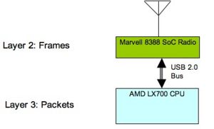
The main concept behind our implementation is that of functional splitting of the networking stack between the WiFi radio and the Host CPU. The ARM processor driving the 88W8388 radio processes Layer-2 frames, while the Host CPU processes packets (IP or any other Layer-3 protocol).
This architecture allows for power savings (since only the Marvell SoC radio is necessary for frame forwarding) and flexibility with upper layer protocols (since it is not depending on any specific Layer-3 protocol - automatically supporting IPv6 for example). It also presents testing challenges in the laptop context since there is no direct user interaction with the ARM processor of the radio.
Testing should concentrate on the following areas:
- Path discovery and management
- Communications integrity
- Performance testing
- Firmware reliability and memory resources management
Given that the implementation is completely distributed, all of the above parameters are stressed as the number of nodes increases. This mandates that test suites are run multiple times with an increasing number of nodes every time.
Path discovery and management
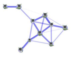
The main purpose of this testing is to ensure proper operation of the core frame forwarding functionality. Assuming a set of nodes with no disconnected members every node should be able to communicate with every other node.
This test can be implemented via a series of any-to-all IP ping sessions with the ping originator mode changing after each set of pings so that all the nodes have the opportunity to originate pings. It is important to have multi-hop topologies during this test so that path discovery and broadcast propagation are exercised. One way to achieve that is to limit the TX power of the radios. Given that the purpose here is to verify frame forwarding, it is desirable that this test is performed in a radio-quiet space so that frame losses due to external radio traffic are minimized. In such an environment, scalability should be tested be gradually increasing the number of nodes (>50).
Communications integrity
Given the complexity of interaction between the firmware on the wireless radio, the driver and the upper networking stack, it is important to test that data streams between applications do not exhibit any corruption. Our experience here indicates that a good way to test that using existing tools is via the use of the SCP command (copy over an SSH encrypted channel) since any bit flipping will trigger checksum errors in the protocol.
SCP implementations exist for all major platforms, so the test is not limited to a Linux host by any means.
Performance testing
With the core functionality established, testing should extend to performance. The first scenario to be tested is the multi-hop chain’s performance characterization.
The test should be performed using the Iperf tool with both TCP and UDP streams between the end nodes of the chain and should be repeated with an increasing number of nodes (1<n<10).
There are two ways to perform this test:
- “lab” environment, where all nodes are close to each other and the topology is forced upon them by means of selective blinding. This is useful to establish upper performance limit expectations for the real world test as well as uncover node-specific issues (driver performance etc.)
- “real” environment where the topology is actually enforced by the radio link range between nodes and where performance will be significantly lower due to the fact the interference range of any node is larger than its communications range (besides the fact that radio links will not be able to operate at maximum speeds).
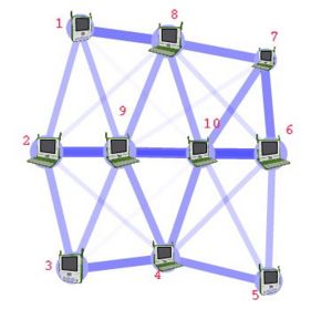
A more complex topology will allow stressing intermediate nodes by having them forward traffic for more than one communication sessions.
In this example concurrent iperf sessions between nodes 1 and 4, 3 and 8, 2 and 10 will stress node 9. It is also important to use this topology to measure broadcast/multicast frame loss rates by means of having every node transmit a set of multicast frames at various rates while their reception is recorded on every other node.
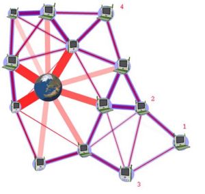
Another important test topology is the dense deployment scenario where, for example, up to 60 laptops in a classroom are trying to access the internet via a single Internet gateway.
In a scenario like this, besides ensuring that laptops can indeed access the internet, what also needs to be tested are potential benefits of multi-hop vs single-hop paths to the Internet gateway given the capability for faster link speeds as well as lower TX power in the multi-hop case.
Firmware reliability and memory resources management
Given the limited amount of memory resources on the radio SoC, it is important to establish that continuous operation for several days in a row is possible. Cycling through the test suite described above for a week at a time will ensure that.
File:802.11s Connectivity Test Plan.doc - Original document
Test cases from Marvell for the OLPC XOs
- Driver / Firmware version
ethtool -i eth0
- Start one OLPC mesh node (node A) with fixed SSID, check beacon for SSID
- Start second OLPC mesh node (node B) with same SSID, and check if it assumes the BSSID of node A. This can be checked from the beacon.
- Give a fixed IP address to Node A and Node B. Then ping node B from Node A. Check if ARP packets are sent by Node A. Check if ARP table is populated with the IP and MAC address of Node B. Check if the ICMP packets are sent correctly. Check if the ICMP replies are received.
- Clear the ARP table of node B. Node ping Node A from Node B. Check if the ARP packets are send from Node B. Check if the ARP table is populated with the IP and MAC address of Node A. Check if the ICMP packets are sent correctly. Check if the ICMP replies are received.
- Start third OLPC mesh node (node C) with same SSID, and check if it assumes the BSSID of node A. This can be checked from the beacon.
- Repeat steps 4 & 5 but replace Node B with Node C.
- Repeat steps 4 & 5 but replace Node A with Node C.
- Start 2 more OLPC nodes to have 5 OLPC nodes. Check if each node transmits a beacon with the same BSSID and SSID of node A.
- Start a ping from each node to any other random node. Check if the pings are properly received.
- Form the machines as each point in a pentagon. Send a ping from one end of the pentagon to the other end. Check if the pings are going through the correct route. Check the RREPs. Check the return RREQ. Check the correct final path.
- Look at the forwarding table to see how many routes are formed to go from one end node to the other.
- Mesh TTL and Mesh E2E Sequence Number should be seen in the Ping Request /Reply packets.
E2E sequence number -> offset 33 in the packet (2 bytes long) TTL -> offset 35 in the packet (1 byte long)
- Observe the route taken by the Ping Request and the Ping Response frames. Disconnect one node from the route and make sure that the route is re-established and the ping still goes through
- Run an iperf test on this linear network and observe the through over a 4-hop network.
- Run through the above steps 15 and 16 with a different network configuration where, on every node, you would blind all the nodes from each other except for the neighbor nodes. If you disconnect one of the neighbor nodes network (basically disable the wireless or just switch off the laptop), you should see that the ping should fail. Deleting any one of the other neighbor nodes from the blinding table should help pings go through fine again because a new route will be formed.
- LED-GPIO connections
WLAN_ENLED (LED 1) -> GPIO01 ->this GPIO should be used for showing that there is association or not. WLAN_ACTLED (LED 2) -> GPIO12 -> this GPIO should be used for showing that there is any traffic or not.
- Configure four MPs (MP1,MP2,MP3 and MP4)
Ensure each node can ping any random node. Configure MP2 to be the MPP and associate it to a Netgear AP(this MPP should have a eth0 as well as a msh0 interface ip).Ensure that MP2 can ping the AP as well as ping all the internal nodes. Run the mpp.py script on the MPP and the mppreq_client script on the MP. Check for the MPP request frame from the MP on the MPP. Now ping the Netgear AP from the MP and check whether the ping goes through.
- Configure two MPPs and have an MP to associate to it. Ping the MPP from the MP. Now turn off one of the MPP and ensure that the MP associates to the other active MPP
- Validated the lsmesh utility
Utility displays all the neighboring nodes connected in the network.
- Configure four MPs (MP1, MP2, MP3 and MP4).Ensure each node can ping any random node. Run pings from any random node to the other and leave it running overnight. Run in open air - not shield room
- Configure four MPs (MP1, MP2, MP3 and MP4)
Ensure each node can ping any random node. Configure MP2 to be the MPP and associate it to a Netgear AP (this MPP should have a eth0 as well as a msh0 interface IP).Ensure that MP2 can ping the AP as well as ping all the internal nodes. Run the mpp.py script on the MPP and the mppreq_client script on the MP. Check for the MPP request frame from the MP on the MPP. Now ping the Netgear AP from the MP and check whether the ping goes through. Run this test overnight. The MPP IP address in both the scripts should be:
- The same
- On the same subnet as the mesh network
- Should be different from the IP address of any other MP or MPP in the mesh subnet.
- Introduce another MPP in the network. Then stop and start all the MPs again. Some MPs should use one MPP and some other should use the other MPP. It is assumed that some MPs are closer to one as opposed the other MPP. This will test whether the metrics used in the MPP Responses are correctly used or not.
- Remove one of the MPs from the network, i.e. gradually walk far away from the mesh network coverage. The rest of the MPs should transmit RERR (Route Error) messages to the nodes that are refreshing their routes to the MP that just walked out of the network.
- Per-peer mesh transmission rate adaptation
Configure three MPs (X, Y, Z) placed close to each other and ping X Y, Y Z, Z X. Take Y physically away from the other two. Then, after sometime, get the Y back again to the original position. The data rate of pings of X Y should decrease first and then increase when Y gets back to original position. Same applies to Y Z. Z X should remain the same throughout the test.
- Configure the MPP to be a gateway and the AP being the DHCP server. Connect a MP (MP1) to MPP. Check if MP1 gets an IP address from the AP.
- Add a new MP (MP2) to the network and check that it gets a new IP address from the AP. Check if MP1 can ping MP2 and vice versa.
- Add a new MPP to the network. Connect another MP (MP3) to the network. Check that it gets an IPaddress from the AP. Check that MP3 can ping MP1 and MP2 and vice-versa.
Subset of mesh testing that can possibly be done at 1CC:
File:OLPC Mesh Test Cases Marvell.pdf


