802.11s Connectivity Test Plan/lang-ko
환영합니다 | Portal | XO Korea | Deployment | Content | Hardware | Software | Mesh Network | Ethics | LOS | XO City | Accreditation | Consortium
OLPC 802.11s 작동 실험 계획
XO 노트북 상에서 Marvell/OLPC 802.11s의 작동을 테스트하는 절차를 체계적으로 기술하는 첫 시도입니다.
[주: 이 문서는 이미 세계 각지에서 수행된 테스트들에 대부분 의존하고 있습니다.]
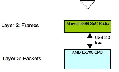
우리의 작동 실험을 뒷바침하는 주요한 개념은 WiFi radio와 Host CPU 간의 네트워킹 스택의 기능적 분할입니다. 88W8388 라디오를 구동하는 ARM 프로세서는 Layer-2을 처리하며, Host CPU는 packets (IP or any other Layer-3 protocol)를 처리합니다.
이러한 아키텍처는 전력 절감 (프레임 포워딩에는 Marvell SoC 만 필요하므로)과, 상위 레이어 프로토톨과의 유연성을 보장합니다 (어떤 특정한 Layer-3 프로토콜에 의존하는 것이 아니라, 자동적으로 IPv6를 지원하는 등).
실험은 아래 영역에 집중해야 합니다.
- 경로 발견과 관리
- 커뮤니케이션 통합성
- 성능 테스트
- 펌웨어 신뢰성과 메모리자원관리
이 실험은 완전히 분산되어 있으므로, 노드 수가 증감에 따라 상기 패러미터들은 스트레스를 받습니다. 따라서, 테스트 슈트는 매번 노드 수의 증가와 더불어 수 차례 수행되어야만 합니다.
경로 발견과 관리
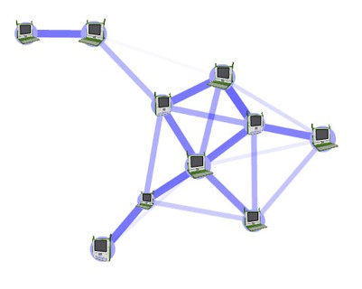
이 실험의 주요한 목표는 코어 프레임 포워딩 기능의 적절한 동작을 확실히 하기 위함입니다. 단절된 멤버없는 일련의 노드들을 가정할 때, 모든 노드들은 다른 모든 노드들과 소통할 수 있어야 합니다.
This test can be implemented via a series of any-to-all IP ping sessions with the ping originator mode changing after each set of pings so that all the nodes have the opportunity to originate pings. It is important to have multi-hop topologies during this test so that path discovery and broadcast propagation are exercised. One way to achieve that is to limit the TX power of the radios. Given that the purpose here is to verify frame forwarding, it is desirable that this test is performed in a radio-quiet space so that frame losses due to external radio traffic are minimized. In such an environment, scalability should be tested be gradually increasing the number of nodes (>50).
커뮤니케이션 통합성
무선 라디오 상의 펌웨어, 드라이버와 상부 네트워킹 스택 간의 복잡한 상호작용을 고려할 때, 어플리케이션 간의 데이타 흐름에 corruption이 없는 지 테스트해야 합니다. 우리의 경험에 의하면, 기존의 툴들을 ㅣ용한 좋은 테스트 방식 하나는 SCP 커맨드SCP command 를 이용하는 것인데 (copy over an SSH encrypted channel), 모든 비트 플리핑bit flipping 은 프로토콜 내에서 체크섬 에러checksum errors 를 발생시키기 때문입니다. SCP 수행implementations 은 모든 주요 플랫폼에 존재하므로, 이 실험이 리눅스 호스트에 한정될 필요는 없습니다.
성능 테스트
기존의 핵심 기능들과 더불어, 테스트는 성능 부문을 포괄해야 합니다. 테스트될 첫 시나리오는 멀티훕 체인multi-hop chain의 성능 특성입니다.
이 테스트는 체인의 최종 노드들 간의 TCP 및 UDP 흐름과 더불어 Iperf 툴을 이용하여 수행되고, 노드 수의 증가와 더불어 반복 수행되어야 합니다 (1<n<10).
이 테스트를 수행하는 두 가지 방식은:
- "연구실" 환경은 모든 노드들이 근접해 있고, 선택적 바인딩을 통한 토폴로지가 그것들에 강제됩니다. 이 것은 실제 세계에서의 최상 성능 제한 기대치를 설정하는 것과 노드에 특정한 이슈들 (드라이버 성능 등)을 밝히는데 유용합니다.
- "실 세계" 환경에서는 토폴로지가 노드들 간의 라디오 링크에 의해 실제로 강제되며, 노드의 간섭 범위가 그것의 커뮤니케이션 범위보다 크므로 성능이 현저히 떨어지게 됩니다.
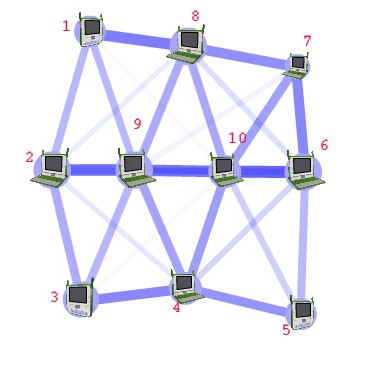
보다 복잡한 토폴로지를 이용해, 중간 노들들이 하나의 커뮤티케이션 세션 이상으로 트래픽을 포워드하게 함으로써 그것들에게 스트레스를 가할 수 있습니다.
이 예에서, 노드 1과 4, 3과 8, 2와 10 간의 동시적인 iperf 세션은 노드 9에 스트레스를 더합니다. 이 토폴로지를 이용하여, 모든 노드들이 다양한 비율로 멀티캐스트 프레임 세트를 전송하고, 그것들의 수용이 각각의 다른 노드 상에 기록되게 함으로써, 브로드캐스트/멀티캐스트 프레임 상실율을 측정하는 것도 중요합니다.
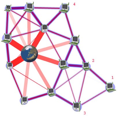
또 하나의 중요한 테스트 토폴로지는 밀집된 분포 시나리오로, 가령, 어느 한 교실 내의 60여 노트북들이 단 하나의 인터넷 게이트웨이를 통해 인터넷에 접속하려고 시도하는 경우입니다.
이러한 시나리오에서, 노트북들이 실제로 인터넷에 접속하도록 하는 것뿐 아니라, 멀티 훕에서 낮은 TX 파워 및 빠른 연결 속도 하에서, 인터넷 게이트웨이로의 멀티 훕 vs 싱글 훕 경로의 잠재적 이점들을 테스트할 필요가 있습니다.
펌웨어 신뢰성과 메모리 자원 관리
라디오 SoC의 제한된 메모리 자원 하에서, 수일 간에 걸친 연속적인 동작이 이뤄질 수 있도록 하는 것이 중요합니다. 한 번에 일주일 씩, 위에서 설명한 테스트 슈트를 통한 사이클링이 이를 확실히 할 것입니다.
File:802.11s Connectivity Test Plan.doc - Original document
OLPC XO 노트북을 위한 Marvell로부터의 테스트 케이스
- Driver / Firmware version
ethtool -i eth0
- Start one OLPC mesh node (node A) with fixed SSID, check beacon for SSID
- Start second OLPC mesh node (node B) with same SSID, and check if it assumes the BSSID of node A. This can be checked from the beacon.
- Give a fixed IP address to Node A and Node B. Then ping node B from Node A. Check if ARP packets are sent by Node A. Check if ARP table is populated with the IP and MAC address of Node B. Check if the ICMP packets are sent correctly. Check if the ICMP replies are received.
- Clear the ARP table of node B. Node ping Node A from Node B. Check if the ARP packets are send from Node B. Check if the ARP table is populated with the IP and MAC address of Node A. Check if the ICMP packets are sent correctly. Check if the ICMP replies are received.
- Start third OLPC mesh node (node C) with same SSID, and check if it assumes the BSSID of node A. This can be checked from the beacon.
- Repeat steps 4 & 5 but replace Node B with Node C.
- Repeat steps 4 & 5 but replace Node A with Node C.
- Start 2 more OLPC nodes to have 5 OLPC nodes. Check if each node transmits a beacon with the same BSSID and SSID of node A.
- Start a ping from each node to any other random node. Check if the pings are properly received.
- Form the machines as each point in a pentagon. Send a ping from one end of the pentagon to the other end. Check if the pings are going through the correct route. Check the RREPs. Check the return RREQ. Check the correct final path.
- Look at the forwarding table to see how many routes are formed to go from one end node to the other.
- Mesh TTL and Mesh E2E Sequence Number should be seen in the Ping Request /Reply packets.
E2E sequence number -> offset 33 in the packet (2 bytes long) TTL -> offset 35 in the packet (1 byte long)
- Observe the route taken by the Ping Request and the Ping Response frames. Disconnect one node from the route and make sure that the route is re-established and the ping still goes through
- Run an iperf test on this linear network and observe the through over a 4-hop network.
- Run through the above steps 15 and 16 with a different network configuration where, on every node, you would blind all the nodes from each other except for the neighbor nodes. If you disconnect one of the neighbor nodes network (basically disable the wireless or just switch off the laptop), you should see that the ping should fail. Deleting any one of the other neighbor nodes from the blinding table should help pings go through fine again because a new route will be formed.
- LED-GPIO connections
WLAN_ENLED (LED 1) -> GPIO01 ->this GPIO should be used for showing that there is association or not. WLAN_ACTLED (LED 2) -> GPIO12 -> this GPIO should be used for showing that there is any traffic or not.
- Configure four MPs (MP1,MP2,MP3 and MP4)
Ensure each node can ping any random node. Configure MP2 to be the MPP and associate it to a Netgear AP(this MPP should have a eth0 as well as a msh0 interface ip).Ensure that MP2 can ping the AP as well as ping all the internal nodes. Run the mpp.py script on the MPP and the mppreq_client script on the MP. Check for the MPP request frame from the MP on the MPP. Now ping the Netgear AP from the MP and check whether the ping goes through.
- Configure two MPPs and have an MP to associate to it. Ping the MPP from the MP. Now turn off one of the MPP and ensure that the MP associates to the other active MPP
- Validated the lsmesh utility
Utility displays all the neighboring nodes connected in the network.
- Configure four MPs (MP1, MP2, MP3 and MP4).Ensure each node can ping any random node. Run pings from any random node to the other and leave it running overnight. Run in open air - not shield room
- Configure four MPs (MP1, MP2, MP3 and MP4)
Ensure each node can ping any random node. Configure MP2 to be the MPP and associate it to a Netgear AP (this MPP should have a eth0 as well as a msh0 interface IP).Ensure that MP2 can ping the AP as well as ping all the internal nodes. Run the mpp.py script on the MPP and the mppreq_client script on the MP. Check for the MPP request frame from the MP on the MPP. Now ping the Netgear AP from the MP and check whether the ping goes through. Run this test overnight. The MPP IP address in both the scripts should be:
- The same
- On the same subnet as the mesh network
- Should be different from the IP address of any other MP or MPP in the mesh subnet.
- Introduce another MPP in the network. Then stop and start all the MPs again. Some MPs should use one MPP and some other should use the other MPP. It is assumed that some MPs are closer to one as opposed the other MPP. This will test whether the metrics used in the MPP Responses are correctly used or not.
- Remove one of the MPs from the network, i.e. gradually walk far away from the mesh network coverage. The rest of the MPs should transmit RERR (Route Error) messages to the nodes that are refreshing their routes to the MP that just walked out of the network.
- Per-peer mesh transmission rate adaptation
Configure three MPs (X, Y, Z) placed close to each other and ping X Y, Y Z, Z X. Take Y physically away from the other two. Then, after sometime, get the Y back again to the original position. The data rate of pings of X Y should decrease first and then increase when Y gets back to original position. Same applies to Y Z. Z X should remain the same throughout the test.
- Configure the MPP to be a gateway and the AP being the DHCP server. Connect a MP (MP1) to MPP. Check if MP1 gets an IP address from the AP.
- Add a new MP (MP2) to the network and check that it gets a new IP address from the AP. Check if MP1 can ping MP2 and vice versa.
- Add a new MPP to the network. Connect another MP (MP3) to the network. Check that it gets an IPaddress from the AP. Check that MP3 can ping MP1 and MP2 and vice-versa.


