Making XO sensors/Lichtsensor: Difference between revisions
Jump to navigation
Jump to search
No edit summary |
No edit summary |
||
| (16 intermediate revisions by the same user not shown) | |||
| Line 1: | Line 1: | ||
:[[Making XO sensors/Making a Light Sensor|< English]] |
:[[Making XO sensors/Making a Light Sensor|< English]] |
||
:[[Making XO sensors/Making a Light Sensor|< Spanish]] |
|||
| ⚫ | |||
* 1 Photowiderstand |
|||
1 Mikrofonkabel (rot: center, schwarz: Erdung, weiß: tip) |
|||
* 1 Lichtsensor [http://www.jaycar.com.au/productView.asp?ID=RD3480], [https://www.radioshack.com/product/index.jsp?productId=2062590], [http://www.parallax.com/Store/Sensors/ColorLight/tabid/175/CategoryID/50/List/0/SortField/0/Level/a/ProductID/175/Default.aspx] |
|||
1 Lichtsensor (siehe Fotos) |
|||
1m Isolierband |
* 1m Isolierband |
||
1 Schere |
* 1 Schere |
||
| ⚫ | |||
* a photoresistor, (light dependent resistor),[http://www.parallax.com/Store/Sensors/ColorLight/tabid/175/CategoryID/50/List/0/SortField/0/Level/a/ProductID/175/Default.aspx] [http://www.jaycar.com.au/productView.asp?ID=RD3480] [https://www.radioshack.com/product/index.jsp?productId=2062590] |
|||
* heat-shrink tubing, 2mm diameter, the length of the photoresistor leads plus about 1cm, |
|||
{| class="wikitable" |
{| class="wikitable" |
||
|- |
|- |
||
| [[Image:Light sensor 01.jpg|400px]] |
| [[Image:Light sensor 01.jpg|400px]] |
||
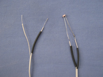
| Wir kappen den Kabelmantel ca. 4 cm und die Drahtisolierung des schwarzen und weißen Kabels (falls es ein drittes Kabel gibt, ignorieren wir es). Anschließend verbinden wir den Lichtsensor mit dem freigelegten abisolierten Draht weiß und schwarz miteinander indem wir den weißen Draht um den einen Draht des Sensors wickeln und den schwarzen Draht um den Anderen. Auf dem Foto sieht man ein Kabel mit lediglich 2 abisolierten Kabeln. |
|||
| As shown in the picture, tear the two ends of the wire apart (as you did when making a plug) and use a Stripper to strip the wire bare. |
|||
[http://de.wikipedia.org/w/index.php?title=Datei:Leitungsende_Abisoliert.svg&page=1&filetimestamp=20120926131700] |
|||
Slide on the X (heat-compressible rubber tubing) onto both ends of the wire as shown. Only one side is shown in the picture, but follow the same process for the other wire. |
|||
Next, use the soldering iron to connect the two ends of the wire to the two ends of the sensor. This can be done by adding some solder to the two end contact points of the sensor and to the bare ends of the wire. Subsequently, join the two together as shown in the picture, and allow the solder to cool, solidify and thus connect. |
|||
|- |
|- |
||
| [[Image:Light sensor 02.jpg|400px]] |
| [[Image:Light sensor 02.jpg|400px]] |
||
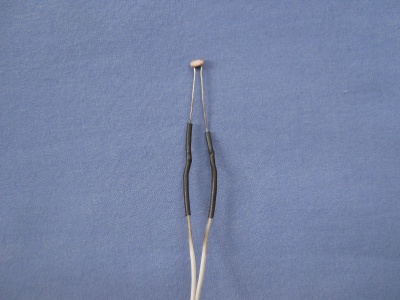
| Anschließend kleben wir mit dem Isolierband die Verbindungsstellen der Kabel mit dem Lichtsensor ab. |
|||
| Next, slide the rubber tubing up the wire so that it completely covers the two contact points, and then use X (hot air) to compress the rubber tubing onto the wire. |
|||
|- |
|- |
||
| [[Image:Light sensor 03.jpg|400px]] |
| [[Image:Light sensor 03.jpg|400px]] |
||
| ''' |
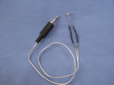
| '''Der Lichtsensor ist nun fertig!''' |
||
| '''Wie gehen wir jetzt vor, um unseren Lichtsensor mit unserem XO zu benutzen?''' |
|||
| Wir öffnen die Activity "Measure" und gehen zu "Capture mode" im Menü und aktivieren den "Resistance Sensor". |
|||
'''Variation:''' |
|||
2 Sensoren mit Model XO 1.5 und 1.75 |
|||
Jetzt verbinden wir den einen Sensor mit dem schwarzen und dem weißen Kabel und den zweiten Sensor mit dem schwarzen und dem roten Kabel. |
|||
Was sehen wir? Was passiert, wenn wir … |
|||
Wir sehen die 2 Lichtsensor-Linien auf dem Bildschirm. |
|||
|} |
|} |
||
Latest revision as of 21:55, 22 October 2012
Lichtsensor Kit:
Other sensor instructions
- Making XO sensors/Construir Sensor Luz
- Making XO sensors/How to connect sensors
- Making XO sensors/Lichtsensor
- Making XO sensors/Making a Humidity Sensor
- Making XO sensors/Making a Light Sensor
- Making XO sensors/Making a Magnetic Sensor
- Making XO sensors/Making a Switch Sensor
- Making XO sensors/Making a Temperature Sensor
- Making XO sensors/Making a Thermistor


