XO 1.5 B2: Difference between revisions
| Line 62: | Line 62: | ||
====Installing from Linux==== |
====Installing from Linux==== |
||
=====On an XO-1===== |
|||
To install on an XO-1.5's SD drive, you can run: |
|||
To install a Linux image onto an SD card inserted into an XO-1, you can run: |
|||
zcat os30.img.gz > /dev/mmcblk0 |
zcat os30.img.gz > /dev/mmcblk0 |
||
=====On an XO-1.5===== |
|||
This becomes a little more complicated on an XO-1.5, as there are two SD card slots and Linux doesn't name them consistently. If there are two SD cards found at boot time, the internal SD slot will be /dev/mmcblk0 and the external SD slot will be /dev/mmcblk1. Otherwise, the SD card found at boot will be named /dev/mmcblk0 and the second card inserted will be /dev/mmcblk1. |
|||
== Restrictions == |
== Restrictions == |
||
Revision as of 05:43, 15 September 2009
XO-1.5 Laptop Beta test model 2 (B-Test 2), also known as B2.
Description
The B2 prototypes are complete systems, externally appearing very similar to production XO-1s (CL1A). OLPC should receive a couple hundred of these in September, 2009.
Identification
- Hopefully identical to a production XO-1 with the single touchpad (CL1A), but with:
- green power and screen rotate buttons
- green battery release buttons
- The motherboard has a daughtercard for the WLAN.
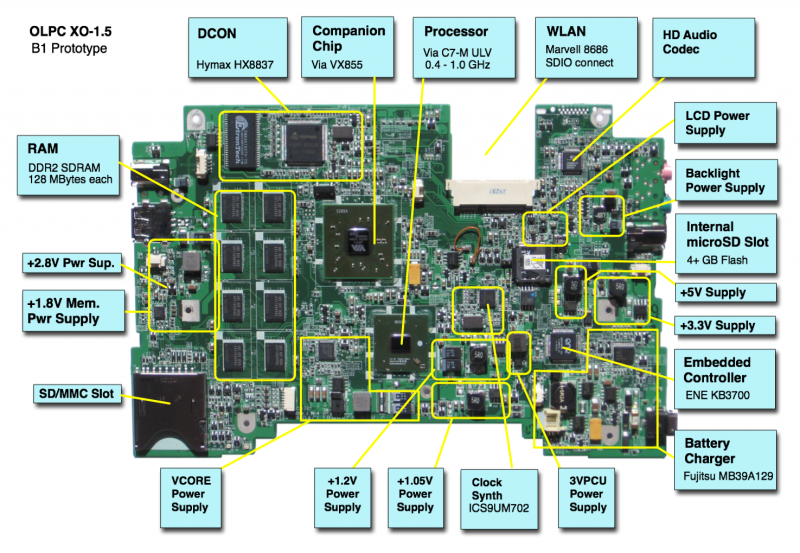
- The motherboard has an internal SD slot
Photographs:
Software Support
Firmware
XO-1.5 use Q3xxx firmware releases. These will not work on an XO-1.
Obtaining Firmware
B2 motherboards require a release equal to or later than Q3A10.
Check the XO 1.5 EC dev changelog for information about the latest EC firmware (integrated into the above OFW releases).
Upgrading Firmware
You can upgrade to a different version of firmware by downloading a new firmware image, then:
- Place the firmware image (.rom) on a USB stick
- Ensure that you have both a somewhat charged battery and a DC power source
- Boot the laptop, pressing the escape key ('X' in upper left hand corner of keyboard) within a few seconds after boot to enter Open Firmware.
- Insert the USB stick containing the new firmware into a motherboard USB port
- Type:
flash u:\q3a10.rom
Linux
We currently provide a Linux build based on Fedora 11, which allows easy switching between a Sugar and a Gnome desktop.
Linux may be installed on the internal microSD card, or on an external SD (or microSD) card. Once installed on a microSD card, it may be used in either the internal socket or the external port (using an adapter).
Obtaining Linux
A Linux image for the A1/A2/B1 is available at http://dev.laptop.org/~cjb/f11-1.5/os27/os27.img.gz. You need os27 or later on a B1, as the DCON is not properly supported and the internal SD card WP is not ignored by the kernel in earlier releases.
Installing from OFW
You will need the .zd version of the OS image. Download it, then:
- Place the image on a USB stick, and insert it into a laptop USB port.
- Boot the laptop, pressing the escape key ('X' in upper left hand corner of keyboard) within a few seconds after boot to enter Open Firmware.
- Type:
fs-update u:\os30.zd
Installing from Linux
On an XO-1
To install a Linux image onto an SD card inserted into an XO-1, you can run:
zcat os30.img.gz > /dev/mmcblk0
On an XO-1.5
This becomes a little more complicated on an XO-1.5, as there are two SD card slots and Linux doesn't name them consistently. If there are two SD cards found at boot time, the internal SD slot will be /dev/mmcblk0 and the external SD slot will be /dev/mmcblk1. Otherwise, the SD card found at boot will be named /dev/mmcblk0 and the second card inserted will be /dev/mmcblk1.
Restrictions
The currently known restrictions on usage are:
Serial Port/Camera
The processor serial port situation on XO-1.5 is not optimal. There is a connector located on the upper left hand side of the motherboard for +3.3V RS-232 connection (see the Pinouts and the Connector/Jumper Locations), but its use must be enabled using a jumper (JP1) located next to it.
To use the serial port: - Install a serial enable jumper - Disconnect the camera. This requires removing the motherboard from the case to access the connector.
The jumper is JP1, but the silkscreen on B1 makes it look like JP12 (there is no JP12).
Documentation
Supporting documentation for these boards are (in PDF):
