Measure: Difference between revisions
m (+OBX pootle) |
|||
| Line 4: | Line 4: | ||
{{ OBX test |[[Tests/Measure|Measure]]<!--|2007-09-18--> }} |
{{ OBX test |[[Tests/Measure|Measure]]<!--|2007-09-18--> }} |
||
{{ OBX devtickets |measure-activity}} |
{{ OBX devtickets |measure-activity}} |
||
{{ OBX pootle|1=http://dev.laptop.org/git?p=projects/measure;a=blob_plain;f=po/Measure.pot;hb=HEAD|2=xobundled}} |
|||
{{ OBX pot |
|||
| root = [[Measure/Localization|Measure]] |
|||
| pot = {{fullurl:Measure/Localization/Measure.pot}} |
|||
| po-root= {{fullurl:Measure/Localization}} |
|||
| es = #es.po |
|||
| others = [{{fullurl:Measure/Localization#pt_BR.po}} pt_BR] }} |
|||
{{ OBX xobundle|http://dev.laptop.org/~arjs/Measure-11.xo|measure v11}} |
{{ OBX xobundle|http://dev.laptop.org/~arjs/Measure-11.xo|measure v11}} |
||
{{ OBX team |Adviser: [[User:Walter|Walter]], Core Development: [[User:arjs|Arjun]], Internationalization: Rafael, Nathalia}} |
{{ OBX team |Adviser: [[User:Walter|Walter]], Core Development: [[User:arjs|Arjun]], Internationalization: Rafael, Nathalia}} |
||
Revision as of 03:08, 25 October 2007
see more templates or propose new |
Introduction
Children learn by doing things. It is said "Give the child a hammer, and the world are his nails".
This activity is a tool that allows kids an expression of their curiosity. It is a tool that allows kids to explore and learn by doing, by connecting and observing span physical phenomena and real world events. Kids would learn by recording and observing the physical phenomena and by connecting their observations to a previously learned concept, or even better - learn the concept based on the experiments and observation.The basic functionality of this activity spans being able to measure DC and AC voltages by observing them on a oscilloscope like interface, being able to watch waveforms in frequency domain (spectrum analyzer), logging data at a specified time interval and drawing the graph of logged data.
Elements of the Measure activity
- There is a 1150 X 800 pixels window in which one sees the waveform. There is a light Grey colored grid in the background which is like the scale.
- Measure Toolbar which allows one to switch between AC and DC modes, Toggle Bias Voltage On/Off, View waveform in time domain or frequency domain, Select frequency range display, and be able to pause waveform on the screen.
- A Log Toolbar which allows one to select the data logging interval, start and stop the logging, display the log
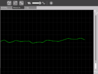
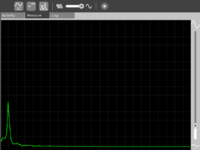
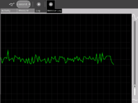
Screen shots of Measure Activity
A short video
<youtube>FE1ufEIXLVo</youtube>
This video is of Release Version 8 of the Activity. The latest release features an improved UI and few more features.
Measure Activity activities
- Record animal sounds , for example, sounds of birds and observe their waveforms. Which of these are high frequency sounds, which are the low frequency ones ? Adjust the frequency sliders accordingly.
- Whistle into the mic and compare the loudness and frequency of whistles by observing the waveforms.
- Turn the sensitivity slider up to the maximum and observe ambient noise - in a quiet room , near a noisy road
- Measure the voltage of an AA size pencil cell. What settings do you use ? AC or DC ?
- Measure resistance of water , other liquids
- Log temperature using a temperature sensor at one hour intervals. When in the day is it the hottest ? The coldest ?
- Some very interesting sensor ideas given by Arnans Roger , see - http://padthai.media.mit.edu:8080/cocoon/gogosite/documentation/makingSensors.xsp?lang=en
(Ideas 1 and 2 given by Erik Blankenship)
Downloading and running the activity on the XO
The link for the latest version of the activity is http://dev.laptop.org/~arjs/Measure-11.xo . Other previous versions can be found at http://dev.laptop.org/~arjs/
To install the .xo bundle, in the sugar shell (do not do this as root) type
sugar-install-bundle <path>/Measure-11.xo
Activity has been found running well on build 575 and higher. Since it is a CPU intensive activity, it works best on B3 and B4 machines. Also pre-B4 machines might not fully support the DC mode.
Measure Projects
- A low cost (possibly $2) probe that would increase the range of voltage that can be applied to the input.
- An ultrasonic distance measurement system that connects to the XO and allows the XO to log data. This has immense applications in water level monitoring in villages and also in robotics applications.
- A general purpose hardware kit that interacts with the measure activity. Something on similar lines to http://www.create.ucsb.edu/~dano/CUI/
- Sensors could be distributed along with the XO as peripherals. The advantage of this would be that the measure activity can be calibrated against the known specs of the sensors.
- Being able to measure resistance
- A low cost version of LEGO mindstorms system built around the XO. The XO has good hardware and software capabilities to achieve this.
- RS232 or serial interface would allow a host of electronic devices to interact and communicate with the XO.
- Build a sensor network using a sensor connected to each XO and utilize the mesh networking capability of the XO. This would give us a highly powerful, robust and reconfigurable sensor network.
- Build medical applications using sensors and the XO. See Eletrocardiogram and http://wiki.laptop.org/go/TeleHealth_Module
- Do some Fablab projects using the XO. See http://fab.cba.mit.edu/labs/vigyan/
- Collaborative music creation over the mesh using the music software on the XOs and giving input from an array of different sensors.
- Integrate sensor input into LOGO / Turtle activity
- Milk purity in rural areas. I remember reading about it in some FabLab's website - I think it requires an ADC, which we have.
- Temperature Monitoring and Logging
- Intrusion Alarm System
Hardware details
The Analog Devices AD1888 sound chip has the ability to sample DC voltages. Experimentally it has been found out that the range is fairly linear, however the range that it can sample is restricted to 0.3V - 1.9V , with all the internal gains turned to the minimum.
The XO hardware has been designed to facilitate measurement of DC voltages by the addition of an electronic switch that can be controlled via a setting on the Alsa mixer called 'Analog Input' . The high pass filter can also be turned on/off by a setting 'High Pass Filter' in Alsamixer. The ability to control V_REFOUT (bias voltage) is also available and is done by the control 'V_REFOUT' in alsamixer.
All the above settings are being handled in the activity by using an os.system("amixer <control name> <mute/unmute>")
For software developers
- See tickets assigned to measure-activity on trac for ways to help out!
Brief overview of the code
- audiograb.py
- drawwaveform.py
- config.py
audiograb.py is the file that takes care of grabbing input audio samples. It uses a gstreamer pipeline in which the handoff signal of the fakesink element is used to intercept the data in the pipeline. Data logging is done in this class since we can use the sampling rate as a time reference; i.e. we know the sampling rate and also the number of elements in each buffer that is intercepted from the pipeline. So each atomic time interval is (1/Fs * bufferSize). This is the time interval after which we get a handoff signal.
drawWaveform.py is the class that handles the waveform drawing part. It creates and uses a cairo context to draw the background, the grid and the waveform. It uses a combination of pango and cairo for displaying the text as it was found out that cairo is itself not good at rendering text. All drawing occurs in the expose function which is the gtk expose event handler. It does drawing from the real time samples or from a file. In real time, it can either draw time domain or display the frequency domain samples. self.integer_buffer is one buffer that is obtained from audiograb.py and self.main_bufers is the buffer that accumulates all these buffers. The self.main_buffers is sampled at varying intervals of time, depending upon the frequency range selected, to form self.buffers which is the buffer that is scaled and drawn. self.main_buffers is sampled at a larger interval (set by self.spacing) for lower frequencies and at a shorter interval for higher frequencies. An example calculation is as follows. If we form 1 self.buffers by taking all consecutive elements, we would be sampling at 48khz. I have found that to draw a reasonable representation of a sine wave, one needs at least 8 -12 points. Hence the largest frequency that can be represented accurately is given by 48/12 = 4Khz, or less.Text is updated after every self.update_text expose events.
config.py contains all global variables.
Signals and timeouts used in the software
The handoff signal in audiograb.py is emitted whenever a new buffer is available. The signal handler is on_buffer which adds a gobject timeout. On timeout, _new_buffer is called which emits a custom signal new-buffer. The signal handler for this custom signal is _new_buffer in drawWaveform. Within _new_buffer, the new buffer is read and saved /stored. The expose event is queued in the main measure.py which causes the expose function to be called.
For content developers
I have yet to work on a to-do task list for the content. However, I wish to develop a complete page around each of the points (and more) enumerated in the Learning activities section mentioned above. Ideally I would want a short illustrative video on each page.
This page presents a solution for electrical signals to be input to the XO. For the corresponding problem on output, no such solution exists, but there are some ideas at Electrical output. One idea there is to use the modem connection as finely-timed output - clearly, this would also work for increasing the number of input signals, though it is probably more useful for timing than for fine measurement.
There is a risk of electric shock resulting in death if the XO is used to measure mains voltage by direct connection. The audio input components are not designed for this and damage is likely to result. The extent of the damage is not easily predictable. The only components intended for mains voltage are the pins of the AC adaptor. Dangerous voltages applied to the audio input may also be emitted on audio output, USB connectors, or the DC power input jack.
Temperature monitoring system
How to build
You need-
- LM35 or any similar temperature sensor
- USB connector
- Audio connector
- Some wire or a cable. You could use cut a USB cable and an audio cable from the middle
- Measure Activity
The USB port has two pins which are of use to us. One is the ground and the other one is the one which provides a constant 5V. When you cut a USB cable in the middle, you could find out by trial-and-error by using a simple Voltmeter which are the two wires corresponding to these two pins. If you don't have a Voltmeter, try using a simple LED and a resistor to do the job.
We provide the +5V that this temperature sensor requires from the USB port. For this we connect the +5V wire to the Vcc of the sensor. We connect the ground to the Ground terminal on the LM35. We connect the Vout of the sensor to the Audio Input jack.
How to operate
Set the Measure Activity to be in the DC Mode and Turn Off the Bias Voltage. Both these can be controlled by using the first two buttons on the 'Measure Toolbar'.
The DC voltage is proportional to the temperature . The voltage that the XO can read varies between 0.9 V - 3V. The output of the sensor would be from 0-5V, so, for for different ranges of temperature one can either use a potential divider for higher ranges or using resistances add a bias to the Vout of the sensor from the +5V of the USB again.
Learn More
The LM35 has an output voltage proportional to the temperature. The scale is 0.1V/C. Read the [Data Sheet] to learn more.
One could log temperature over a period of time - say at an interval of 1 hour for a complete day to know when is it the hottest / coldest.
Video
(put video with flame demonstration here, put pictures here - including ckt diagram)
Intrusion Alarm system
How to build
You need-
- A toy laser
- An LDR or a Photo-Voltaic cell
- Some wire
- Measure Activity
Open up the toy laser and remove the batteries. Connect a wire to the spring inside and connect the other wire to the metallic body inside. Connect both of these wires to the USB power supply wires. Click here to learn about how to determine the USB power supply lines.
Connect the LDR to the Audio Jack.
How to operate
Set the Measure Activity into DC Mode and turn ON the bias voltage. Setup the LDR and the laser to be in line and facing each other. When the path of the laser light gets cut, you should observe a marked increase in voltage indicated by the position of the waveform shifting up.
Learn More
The resistance of the LDR - Light Dependent Resistor is proportional to the amount of light falling on it. The potential drop across the LDR is dependent on the resistance of the LDR. When the path of the light gets cut, the resistance increases hence we notice a marked increase in voltage indicated on the screen.
Click here to know more about Bias Voltage and how it works.
Video
Put a video here and some pics
Acknowledgments
Thanks to Mitch Bradley and John Watlington for their help and suggestions during the development of the Activity.


