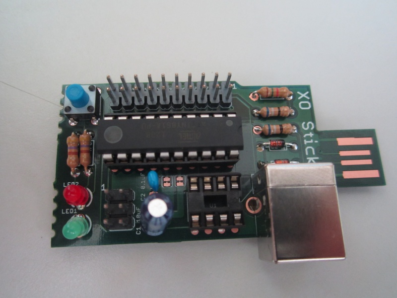
XO Stick
Assembly notes
- break off the 2 tabs and glue (superglue? cyanoacrylate?) them to the plug on the non copper side to make the board thick enough to plug into a USB connector
- LEDs are polarized, flat side should be down (towards big USB port)
- Zener diodes are polarized, make the black stripe match the stripe on the board
- The large capacitor is polarised, observe the +- marks
- The IC's are 'polarised' the notch on the PCB and socket match the dot (pin 1) of the IC
- The board supports either the Attiny 85 (8 pin) or 861 (20 pin) IC, but not both plugged in at once
- All? the components are mounted on the board top (the side with the white labels)
- You probably will want to install the Arduino boot loader on the IC
The assembled board, note the orientation of the IC, LEDs, diodes and big capacitor
Programming
AVR Stick firmware will work unmodified (for the ATtiny85 version): http://www.sparkfun.com/products/9147
Sample programming command:
avrdude -c usbtiny -pattiny85 -U flash:w:main.hex -U hfuse:w:0xdd:m -U lfuse:w:0xe1:m
Or "make fuse program" from the AVR Stick source distribution.
Do this as root if you need to (then go fix your udev by adding something like the following as /etc/udev/rules.d/10-usbtiny.rules
SUBSYSTEM!="usb|usb_device", GOTO="usbtiny_rules_end"
ACTION!="add", GOTO="usbtiny_rules_end"

ATTRS{idVendor}=="1781", ATTRS{idProduct}=="0c9f", MODE="0664", GROUP="plugdev"

LABEL="usbtiny_rules_end"
Would be nice to eventually have an assembly guide as detailed as the one for http://www.sparkfun.com/products/10547
C. Scott's other notes
Notes on v5:
- ATtiny261A should be at least ATtiny461a if not ATtiny861a, since USB library takes up 2496 bytes.
- full size USB convert to mini or micro? (no through-hole micro-B connectors?)
- LED1/LED2 need better polarity mark (flat side is down, towards big usb port)
- use '-kit' suffixed versions of footprints (solder mask on component side)
- break off tab appears to work well.
- island between tabs should be anchored to body, not tabs?
- can we avoid anchors on break off tabs, instead use central anchor?
  ie.
    T
 ------------
|            |
 --          \--
TXT|            |
 --          \--
|            |
 ------------
    T
where T indicates tabs.
- remove symmetry from USB connector placement to allow two tabs on XOrduino board. (ie, move connector all the way down)
Distribution
1. cjb
2. cjb
3. Steve Pomeroy
4. Quozl
5. Mike Lee
6. Pippin Wallace
7. Pippin Wallace
8. Sridhar Dhanapalan
9. Tony Forster
10. Javier Andres Galaz Jeria
11. Alan Jhonn Aguiar Schwyn
12. Stephen Thomas
13. Ricardo Moran
14. George Hunt
15. Juan Cubillo
19. cscott (no pcb)
Sources
http://github.com/cscott/xostick -- look at the "A1" tag for the schematics for the A1 boards. Latest XO Stick is at HEAD, targetted for the B1 build.
See also
Links
http://www.sparkfun.com/datasheets/Widgets/AVR-Stick-v12.pdf indicative circuit diagram XOstick1
https://github.com/cscott/xostick/blob/master/XO-Stick2-sch.pdf circuit diagram XOstick2
http://arduino.cc/en/Tutorial/ArduinoISP programming the bootloader with another Arduino
https://www.sparkfun.com/products/9825 pocket programmer
http://www.atmel.com/Images/doc2586.pdf datasheet Attiny85 (the 8 pin chip)
http://www.atmel.com/Images/doc2588.pdf datasheet Attiny861 (the 20 pin chip)
https://github.com/cscott/xostick circuit board artwork, drill table, bill of materials and notes
https://groups.google.com/forum/?hl=en&fromgroups#!forum/xorduino Google interest group
http://cananian.livejournal.com/66129.html and http://cananian.livejournal.com/66654.html blog
http://www.sparkfun.com/tutorials/106 a soldering tutorial
