XO Stick
Background
The XOrduino! and XO Stick are Arduino compatible single board computers. A blank circuit board for each is included with every XO-4 touchscreen computer. These boards can be populated with inexpensive (US$5 approximately) components. Some soldering skills are required, the XOstick is recommended for beginners because it has no surface mount components.
The boards can be used in robotics experiments in two ways:
- Install the Arduino IDE in Gnome or Terminal and use it to program the Arduinos as stand alone robotics experiments
- Load the Arduino with Firmata software (once only using the Arduino IDE) and use the Arduino as an Input/Output board for Turtle Art
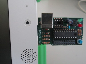
The XO Stick includes a USB type A plug and can be plugged in to an XO, as shown in this photograph.
A USB type B socket can be added; it is the metal rectangle in the photograph. This USB type B socket can be used with a USB type A to B cable, allowing the XO Stick to be further from the XO, and reducing the risk of the XO Stick breaking off in the XO socket.
Out of Date
The assembly notes and parts list here are somewhat out of date.
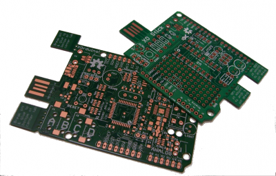
This image shows the newer XOrduino and XOstick boards. The latest version of the XOstick board (v8) has no surface mount parts, and is an entirely PTH (through-hole) design.
Parts list
Required: (pick 1 of U1/U2)
- 1,493-5946-ND,C1 10uF
- 1,478-5741-ND,C2 0.1uF
- 2,1N5226BFSCT-ND,D1 D2 3.3V Zener
- 2,CF14JT68R0CT-ND,R1 R2 68 ohm
- 1,CF14JT1K50CT-ND,R3 1.5k ohm
- 1,ATTINY85-20PU-ND,U1
- 1,ATTINY861-20PU-ND,U2
Recommended:
- 1,754-1217-ND,LED1 T1 Green
- 1,754-1218-ND,LED2 T1 Red
- 2,CF14JT470RCT-ND,R4 R4 470 ohm
- 1,450-1652-ND,SW1 6mm
As seen in the photo, if you use a socket for the ICs(U1 & U2), you can get both and swap them.
Assembly notes
- Break off the 2 tabs and glue them to the plug on the non copper side to make the board thick enough to plug into a USB connector. Cyanoacrylate, commonly known as "superglue", works well. Use as little glue as possible -- together, the three layers of board (at .8mm each) exactly match the nominal USB specification for the plug thickness (i.e., 2.4mm). Too much glue will make the connector not fit. In addition, clamp the three layers tightly while the glue dries, to keep the gaps small.
- When choosing components, note that the holes for the component leads are sized for modern, tiny, components. The old 1/4W resistors in your junk tray, or the LEDs you've been saving for 10 years until you have a use for them, might not fit.
- LEDs are polarized, flat side should be down (towards big USB port). The LEDs are optional, but at least one can be quite useful.
- Zener diodes are polarized, make the black stripe match the stripe on the board. If the USB will never be used, for programming or in operation, then the zeners are optional.
- The large capacitor is polarized, observe the +- marks.
- The IC's are 'polarized' the notch on the PCB and socket match the dot (pin 1) of the IC.
- The board supports either the Attiny 85 (8 pin) or 861 (20 pin) IC, but not both plugged in at once.
- All the components are mounted on the board top (the side with the white labels)
- You probably will want to install the Arduino boot loader on the IC
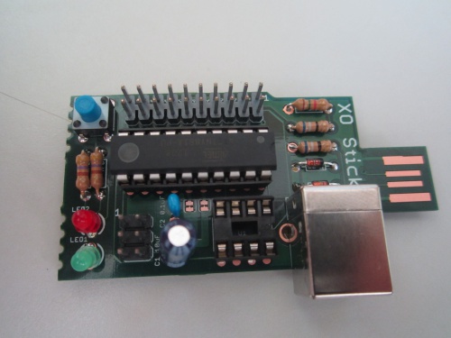
The assembled board (an early version, lacking the prototyping area of later editions). Note the orientation of the IC, LEDs, diodes and big capacitor - IC dot top right, LED flat sides bottom, diode bar to the right and capacitor "-" to the bottom.
Burning the bootloader
There is no stable bootloader yet but in theory you can burn the bootloader onto an unprogrammed ATTiny IC (8 or 20 pin) with another Arduino XO_Stick/Bootloader
Programming
AVR Stick firmware will work unmodified (for the ATtiny85 version): http://www.sparkfun.com/products/9147
Sample programming command:
avrdude -c usbtiny -pattiny85 -U flash:w:main.hex -U hfuse:w:0xdd:m -U lfuse:w:0xe1:m
Or "make fuse program" from the AVR Stick source distribution.
Do this as root if you need to (then go fix your udev by adding something like the following as /etc/udev/rules.d/10-usbtiny.rules
SUBSYSTEM!="usb|usb_device", GOTO="usbtiny_rules_end"
ACTION!="add", GOTO="usbtiny_rules_end"

ATTRS{idVendor}=="1781", ATTRS{idProduct}=="0c9f", MODE="0664", GROUP="plugdev"

LABEL="usbtiny_rules_end"
Would be nice to eventually have an assembly guide as detailed as the one for http://www.sparkfun.com/products/10547
C. Scott's other notes
Notes on v5:
- ATtiny261A should be at least ATtiny461a if not ATtiny861a, since USB library takes up 2496 bytes.
(similarities: introduced in 2006, uses 'avr25' GCC arch id, 16 I/O Pins, 1 USI,1 8-bit counter, 1 16-bit counter, 2x2 PWM, 8ch/11b ADC, 20 MHZ max clock speed)
| ATTINY | Bytes of Flash | Bytes of RAM | Bytes of EEPROM |
|---|---|---|---|
| 261A | 2048 | 128 | 128 |
| 461A | 4096 | 256 | 256 |
| 861A | 8192 | 512 | 512 |
(cost: from 85 cents to 1.72 $ based upon qty)
- full size USB convert to mini or micro? (no through-hole micro-B connectors?)
- LED1/LED2 need better polarity mark (flat side is down, towards big usb port)
- use '-kit' suffixed versions of footprints (solder mask on component side)
- break off tab appears to work well.
- island between tabs should be anchored to body, not tabs?
- can we avoid anchors on break off tabs, instead use central anchor?
  ie.
    T
 ------------
|            |
 --          \--
TXT|            |
 --          \--
|            |
 ------------
    T
where T indicates tabs.
- remove symmetry from USB connector placement to allow two tabs on XOrduino board. (ie, move connector all the way down)
Distribution
1. cjb
2. cjb
3. Steve Pomeroy
4. Quozl
5. Mike Lee
6. Pippin Wallace
7. Pippin Wallace
8. Sridhar Dhanapalan
9. Tony Forster
10. Javier Andres Galaz Jeria
11. Alan Jhonn Aguiar Schwyn
12. Stephen Thomas
13. Ricardo Moran
14. George Hunt
15. Juan Cubillo
19. cscott (no pcb)
Sources
http://github.com/cscott/xostick -- look at the "A1" tag for the schematics for the A1 boards. Latest XO Stick is at HEAD, targetted for the B1 build.
See also
Links
http://www.sparkfun.com/datasheets/Widgets/AVR-Stick-v12.pdf indicative circuit diagram XOstick1
https://github.com/cscott/xostick/blob/master/XO-Stick2-sch.pdf circuit diagram XOstick2
http://arduino.cc/en/Tutorial/ArduinoISP programming the bootloader with another Arduino
https://www.sparkfun.com/products/9825 pocket programmer
http://www.atmel.com/Images/doc2586.pdf datasheet Attiny85 (the 8 pin chip)
http://www.atmel.com/Images/doc2588.pdf datasheet Attiny861 (the 20 pin chip)
https://github.com/cscott/xostick circuit board artwork, drill table, bill of materials and notes
https://groups.google.com/forum/?hl=en&fromgroups#!forum/xorduino Google interest group
http://cananian.livejournal.com/66129.html and http://cananian.livejournal.com/66654.html blog
http://www.sparkfun.com/tutorials/106 a soldering tutorial
http://digistump.com/wiki/ The XO Stick should be roughly compatible with the "DigiSpark"


