XO 1.75 B1
XO-1.75 Laptop Beta test model 1, also known as B1.
Description
The B1 are the fourth prototypes of the XO-1.75 built. Electrically, these are very similar to the A3 prototypes. Several hundred were made in July, 2011, for distribution to software developers.
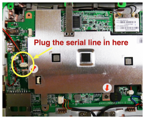
Due to a flaw in the security system, each laptop bricked itself ten days after manufacture. The fix is to connect a serial cable and flash a new version of firmware after Q4B05. See XO 1.75 11089 Fix for how to fix, and see <trac>11089</trac> for technical details.
Remember, this is a prototype, there are design faults. See below for hardware restrictions. See http://dev.laptop.org/1.75 for tickets that are not closed, in the XO-1.75 firmware or software milestones.
Identification
These are the first fully assembled XO-1.75 laptops. While production 1.75 laptops will be identifiable by two rows of raised dots on the hinge cover, B1 laptops only have three dots (identical to the XO-1.5).
One way of identifying them is the slow blink of the WLAN LED when they are associated, due to the Outdoor Light Sensor turning the LED off to take a reading (this was moved to the storage LED in C1).
Two versions were built:
- Motherboard ID 1B1 --- these units do not have an internal full-size SD card slot, and instead provide SDRAM for use by the DCON. These units are assembled into a green/white case with a non-membrane keyboard. Some of these units are also equipped with a multitouch-capable projected capacitance touchscreen to be used as XO-3 development kits (no touchscreen is planned on XO-1.75).
- Motherboard ID 1B2 --- these units have an internal full-size SD card slot, but no SDRAM for the DCON. These units are assembled into green/white cases with membrane keyboards.
Both versions use internal eMMC for Linux.
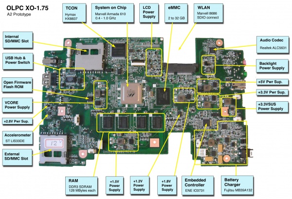
Photographs:
If you disassemble the laptop (instructions), you will see:
Software
See XO-1.75 software.
Software Restrictions
See XO-1.75 general software restrictions. The only XO-1.75 B1 specific software restrictions are:
- a slower accelerometer data rate, (see below).
Firmware Restrictions
White Screen
If you just unwrapped an XO-1.75 B1, tried to boot it, and got a white screen, you're experiencing <trac>11089</trac>. Instructions for fixing this are here. The fix is permanent.
White Screen with XO only, then reboot
Q4B08 and earlier did not indicate when EC reflash was in progress. Fixed in Q4B09. <trac>11117</trac>.
Hardware Restrictions
There is a list of recommended modifications (ECOs). There is also a list of changes proposed from B1 to C1.
Possibility of Shorting Vin
If a large force is applied to the back panel, near the DC power input, there is good chance that the heat spreader will short the main internal power rail. This can be prevented by placing a piece of tape (electrical or cellulose) on the underside of the heat spreader, on the corner nearest the DC Power jack (photo)or the factory fitted modification photo.
If Vin is shorted with the main battery present, the main battery may act very dead (even if fully charged) until the laptop applies power to it again.
Occasional Accelerometer Hangs
We did not get a hardware fix for <trac>11041</trac> or <trac>10882</trac> onto the B1. A software fix was applied which should prevent this problem from happening, by lowering the data rate, and is present in OFW Q4B05 and kernel in os36.
Antitheft
The antitheft circuitry, by default, does not prevent reprogramming the OFW SPI Flash. It will prevent reprogramming of the EC. Fixing this is a trivial ECO.
Operation w. Solar Cell
Twenty-eight of the motherboards don't have the right resistor values for operation with a solar panel. These should be units with both a touchscreen and a non-membrane keyboard. If you have problems using a solar panel, please contact wad or Richard.
Documentation
Supporting documentation for these boards (all in PDF):
- Pinouts
- Connector Locations
- GPIO Mappings
- EC Pinout
- Component locations: bottom, top
- Unbricking using CForth and using JTAG.
- It is possible to run the SoC at a different core voltage
Please note that production boards may have different pin mappings and connector locations.

