XO-1/Software specification
| Please copy/paste "{{Translationlist | xx | origlang=en | translated={{{translated}}}}}" (where xx is ISO 639 language code for your translation) to XO-1/Software specification/translations | HowTo [ID# 296954] +/- |
XO-1 Software Specification
Introduction and Related Material
Careful stewardship of battery power is critical.
OLPC power management is a work in progress.
- Hardware Power Domains
- Power Management Software
- XO Power Management Tips and Tricks
- LX Power Measurements
- Misc. Papers on Energy Efficiency in Computing and Networking
In addition to effectively managing the power that is in the battery. The Battery and power page discusses many alternate power sources that could be used to supplement the existing charger.
Linux's Approach to Power Control
Linux is highly cross platform, running on just about all significant architectures, including many that are used for battery powered embedded systems. The infrastructure for power management has therefore become quite sophisticated over the last years, though it is still maturing. This means that the facilities are general, and not tied to any particular architecture. The generation one OLPC system, being from the x86 part of the world, is therefore similar and fundamentally different from other x86 based systems, for reasons that will become clear in the discussion below.
Linux is not dependent on ACPI or the older APM power management systems, which are x86 specific. As such, Linux's design has always done its power control in the operating system, and ACPI and the like are considered "platform dependent".
OLPC's Innovations
The DCON chip lets us take over refresh of our very low power flat panel and therefore completely power off the processor board. Given our flat panel is usable in gray scale mode at .1 watt, you can see that the leakage currents and power supply power consumption of the system board can dominate power consumption easily.
We are also able to leave the Marvell wireless module to operate independently, forwarding packets in the mesh while possibly everything else is powered down.
Hardware Configuration
CPU Support
More information about the CPU can be found at Wikipedia and AMD.
- BTest-1 and BTest-2 systems both use the AMD Geode GX-400
- BTest-3 and later systems will all use the AMD Geode LX-700
AMD Geode™ CS5536 Companion Device
All XO-1's use the AMD 5536. Note that the processor and southbridge chips both have extensive facilities to either automatically or under program control save power. Examples include the ability to power down the GPU when not in use, and turn off the video output.
Memory Support
The XO-1 uses soldered down memory on the mother board and cannot be expanded.
- BTest-1 systems all have 256M of RAM and 512M of flash.
- BTest-2-1 systems all have 128M of RAM and 512M of flash.
- BTest-2-2 systems all have 256M of RAM and 512M of flash.
- BTest-3 and later systems will all have 256M of RAM and 1GB of flash.
Video RAM
Video display memory on the XO-1 is taken from main memory. LX-based systems use 16 megabytes of main memory for display purposes, GX-based systems use 8 megabytes.
System Resources
IRQ Map
| System Interrupt | Function |
|---|---|
| IRQ0 | System Timer |
| IRQ1 | PS2 Keyboard |
| IRQ2 | Cascade from Second PIC |
| IRQ3 | SCI |
| IRQ4 | UART1 (internal, for debugging) |
| IRQ5 | AC 97 Audio |
| IRQ6 | DCON |
| IRQ7 | Available |
| IRQ8 | Real time Clock (RTC) Interrupt |
| IRQ9 | Available |
| IRQ10 | USB host controllers |
| IRQ11 | NAND/SD card/Camera |
| IRQ12 | PS2 Touch Pad |
| IRQ13 | Math processor |
| IRQ14 | AES and GPU in LX CPU |
| IRQ15 | Available |
Interrupt Routing
The following diagram should help in understanding interrupt routing in the XO-1.

DMA Resource Assignments
OLPC does not use legacy ISA DMA. All DMA is done via PCI bus mastering, so fixed resource allocation is not necessary.
Keyboard Support
The physical keyboards are all identical on any XO-1; the firmware manufacturing information indicates which variant of keyboard is installed. We use a 3.3V version of a PS/2 interface to save power. There is no provision for plugging in external PS/2 devices.
Keyboard Power
The keyboard and touchpad are powered up continuously in both fully-operational and suspended-to-RAM states (BTest-3 or later) so the keyboard can trigger a resume of the processor. On BTest-1 and BTest-2 the keyboard is not powered during suspend, due to a design oversight.
Keyboard Languages Support
Language support for a keyboard involves several items:
- The legends printed on the keycaps
- XKB definitions for keyboard for the window system that defines the behavior of the keyboard. These are found in /usr/share/X11/xkb.
- A console mapping of the keyboard (generally simpler than the full X Window System keyboard definition, since the console is not fully internationalized.
- Possibly input methods for Amharic, Tigrigna, Vietnamese, Chinese, Japanese, Korean, and IPA.
A single keyboard design is capable of supporting multiple languages, and switching from one language to the other.
At this time, keyboard designs have been completed for the following areas:
- Arabic
- Brazilian Portuguese
- French
- Nigeria (for English, Hausa, Yoruba)
- Spanish
- Thai
- Urdu
- US International (able to be used for many western European languages)
A more current listing of keyboard designs can be found on the Category:Keyboard page.
Which keyboard is installed is encoded in the manufacturing area of the firmware, and the correct keyboard language support installed on software installation.
Additional keyboard definitions are easy to generate: input methods for complex script input may be more involved (though many already exist).
Touchpad
The touch pad/tablet can be "recalibrated" under program command as of BTest-3 (maybe also BTest-2-2). This readjusts the sensitivity of the capacitive sensor. #1407 is being used to track implementation of this power related feature. As a temporary measure, recalibrating the touch pad can be forced manually.
Wireless Hardware
The XO-1 supports 88W8388+88W8015, 802.11b/g compatible; dual adjustable, rotating coaxial antennas; with diversity reception. It also supports an implementation of the evolving 802.11s mesh network draft standard.
The power consumption of the Marvell wireless module has been measured at just over 300mw; even with power supply losses, we expect the batteries can power the wireless for > 40 hours (to be measured).
Since the "last kilometer" problem is so great, we are engineering the system to leave the wireless active for as much of the time as possible, since the wireless can run the mesh network autonomously. The module is capable of waking up the CPU via the embedded controller. #1060 has been established to track the development, integration and verification of autonomous mesh mode.
The wireless firmware dynamically adjusts transmit power, but signal processing in receive dominates power consumption. Marvell has done extensive work to minimize power consumption automatically.
Therefore, we expect to leave the wireless active in all modes except fully powered down (labeled state 1 below); this state also allows us to turn off the USB entirely as there is a signal from the wireless module that allows the XO-1 to be woken up by the wireless firmware.
Additionally, there needs to be an "airplane" mode to meet FAA and similar emissions requirements for on board airplane use, in which the wireless can be disabled. This will not be easy to access, by deliberate design. #1406 is being used to track this issue.
Embedded controller
The embedded controller, an ENE KB3700: File:KB3700-ds-01.pdf, is used to charge the battery, emulate various legacy devices (e.g. PS/2), add more GPIO pins (since the Geode does not have enough pins, some signals have to be routed through the EC), boot the system (the SPI flash used to store the firmware is a serial ROM attached to the EC), wake up the system under various circumstances, and other miscellaneous functions. The EC specification contains detailed information about the commands and protocol used to communicate with the EC. A number of buttons (game pad and buttons, etc.), are interfaced to the EC, and also generate scan codes as though they were keyboard keys, to simplify the programming interface. SCI events are also generated at times to inform the CPU of events, so that the XO-1 can avoid polling interfaces that would otherwise require periodic wake ups.
See also OpenEC
Status Indicators
The XO-1 has a number of status indicators; some of which are on both sides of the main unit.
The picture to the right

of a BTest-2 system has most of these, though some
will be used in a different fashion than the current use. The final production XO-1 systems will lack the keyboard lights in the picture and add indicator lights for the microphone and camera. A labeled picture of a BTest-3 system will be added as soon as possible (sometime in the last two weeks of May).
Wireless Lights
There are two wireless lights. One light looks roughly like an exclamation point, and the other like (*). These are used to indicate connectivity
- The ! LED is used to indicate association *and* connectivity via infrastructure mode.
- XO-1 only: the (*) LED is used to indicate similar association *and* existence of a mesh portal.
- XO-1 only: if neither is lit, then you are trying to use a mesh that is not connected.
- XO-1 only: if both are lit, then you know you are a mesh portal for a mesh to the internet.
Note that this behavior has not been implemented yet, and will require work in the NetworkManager daemon, as it is probably the best place that knows if connectivity is available. See #1385 to track progress.
Power Indicator LED
Indicates power state.
- if the LED is green, the laptop is on and running,
- if the LED is off but flashing every few seconds, the laptop is on but suspended, ready to be woken,
- if the LED is off, the laptop is off.
The LED is controlled by the embedded controller.
Battery LED
The battery LED indicates information about the battery.
- if the LED is green, the external supply is on, and the battery is fully charged.
- if the LED is orange, the external supply is on, and the battery is charging.
- if the LED is red, the battery is low.
- if the LED is flashing red/orange then the battery voltage is critically low, (only minutes left).
- if the LED is flashing orange in a pattern of 4 blinks, pause, 4 blinks, pause... the battery is in trickle charge.
- if the LED is flashing red, there is a problem with the battery charging system or the motherboard.
The "orange" color may be seen as yellow.
This LED is controlled by the embedded controller's battery charging logic.
Microphone LED
If the microphone is enabled, the microphone LED is lit. This is a hardware feature than cannot be circumvented.
Camera LED
If the camera is powered on, the camera LED will be lit. This is a hardware feature than cannot be circumvented.
Firmware (aka BIOS on conventional PC's)
Open Firmware
Rather than using a conventional BIOS and boot loader, as of the "C" series of our firmware we are solely using Open Firmware (OFW). We no longer use LinuxBIOS for the setup of our systems. Fast path resume from RAM requires setting up the entire system: once you have implemented this, setup of the system initially is almost identical.
We have also removed VSA and VESA support (the Geode Virtual Systems Support) from our firmware. Since our PCI bus is fixed, we have no need for PCI configuration registers. Similarly, using the fbdev driver on Linux, we have no need for VESA emulation; while the PCI bus emulation was free software (AMD had generously made it available), the VESA emulation was the one part of VSA that they did not own, and we did not have source for it. We did not want an unneeded unmaintainable binary blob in our firmware, and removing VSA and VESA support saves space in the flash for other purposes.
Fast Resume
Resume on our system is extremely fast: even without any serious attempt to optimize resume, we can resume from RAM in 160 milliseconds (mid-April, 2007). We are still determining the minimum resume time, as a 63ms delay we thought was required has a workaround in the Geode. B3 and later systems are probably similar to the GX. We will work in the future to further speed resume. Note that for most uses, 100ms is considered at the edge of human perception (e.g. typing).
System Identification
The Manufacturing Data page documents the Model ID string, part number, localization information, factory, BIOS version, and many other pieces of data.
Quiet Boot
Boot is "quiet" and uses Linux facilities to make a splash screen at boot overlay the boot messages. Ticket #1394 tracked the implementation of this feature.
POST (Power-On Self Test)
If the screen lights up and OLPC logo appears, a large part of the machine is functioning correctly. Progress reports for earlier startup steps require internal access to the system, using either special serial port or "port 80" hardware adapters.
The normal boot sequence tries to load the OS as fast as possible from the most-likely devices. It typically takes only a few seconds, so it is difficult to read the information that is displayed on the screen.
You can override the fast boot sequence by pressing a game key (any of the four buttons above the power button) right after turning on the power, holding it down until the screen lights up. See Cheat Codes for what each key may mean. In response, OFW displays: "Release the game key to continue", waits for the key to be released, and then starts in interactive mode. In interactive mode, OFW enables the keyboard, probes for USB devices (which might include a USB keyboard), and gives you the opportunity to interrupt the 3-second auto-boot countdown. To interrupt it, type the Escape key (the upper left key on the main keyboard, whose legend is an X inside a disc). (If a USB keyboard is attached, type on it instead of the main keyboard.)
OFW displays an "ok" prompt to indicate it is ready for a command.
The first line of banner text shows the hardware version, amount of memory and serial number of the machine. The second line shows the system signature string, which includes the firmware version. In the example below, the firmware version "Q2C11".
It then reports a number of progress messages, as in this example:
 OLPC B2, 128MB memory installed, S/N SHF70400BD
OpenFirmware CL1 Q2C12 Q2C
Release the game key to continue
Interactive boot
Keyboard probe
USB probe
USB2 devices:
/pci/usb@f,5/wlan@3,0
USB1 devices
Type the Esc to interrupt automatic startup
type 'help' for more information
ok █
OLPC B2, 128MB memory installed, S/N SHF70400BD
OpenFirmware CL1   Q2C12  Q2C

Release the game key to continue
Interactive boot
Keyboard probe
USB probe
USB2 devices:
/pci/usb@f,5/wlan@3,0
USB1 devices
Type the Esc to interrupt automatic startup
type 'help' for more information

ok █
To perform more extensive hardware diagnostics, type "test-all".
ok test-all
Open Firmware Command Prompt
Type "help" at the ok prompt for a list of the most common OFW commands. The OFW FAQ gives additional information about OFW.
Booting
OFW depicts the booting progress with a sequence of icons showing the devices that it is trying to access.
OFW can currently boot from the following media:
- Internal NAND Flash (using the JFFS2 file system)
- SD memory card (using EXT3 or FAT file systems)
- USB mass storage (FLASH key or disk drive) (using EXT3 or FAT file systems)
- USB (wired) ethernet (using TFTP, NFS, or HTTP protocols)
- Wireless network (via infrastructure mode or mesh) See #1431 for wireless boot and installation.
The normal fast-boot sequence - if you do not press a game key after power on - is:
- SD memory card
- Internal NAND flash
- USB (wired) ethernet
- Wireless network
The appropriate icon is displayed as the device is scanned.


If you do press a game key after power on (and do not type "Esc"), the boot sequence is:
- SD memory card
- USB mass storage (FLASH Key or disk drive)
- Internal NAND flash
- USB (wired) ethernet
- Wireless network
The appropriate icon is displayed as the device is scanned.

When OFW succeeds in loading a boot file from a device, it displays the XO icon  and executes that file. The icon just to the left of the XO shows which device succeeded.
OFW on OLPC does not load the operating system in one step. Instead, it first loads a file named "/boot/olpc.fth", containing an executable script written in the Open Firmware command language. The script typically sets up command line arguments for Linux and tells OFW to load the final operating system image from another file. For special circumstances, the script can do other things such as performing system updates or running manufacturing diagnostics.
In the normal case, you will see two occurrences of the pair of icons (device icon, XO icon). The first pair shows successful loading of the olpc.fth script, the second the final loading of the operating system.
The several-second delay that occurs during the first attempt to load from NAND FLASH is caused by the need to scan the entire NAND device in order to mount the JFFS2 filesystem. This is a well-know characteristic of JFFS2 that is not specific to the firmware.
Device Tree
Hardware configuration information is exposed to Linux via the OFW device tree. This facility is also used on PPC and SPARC architectures. OLPC is working with others in the community using the device tree to try to come to a common implementation. #1559 is used to track this unification between users of the device tree interface in Linux.
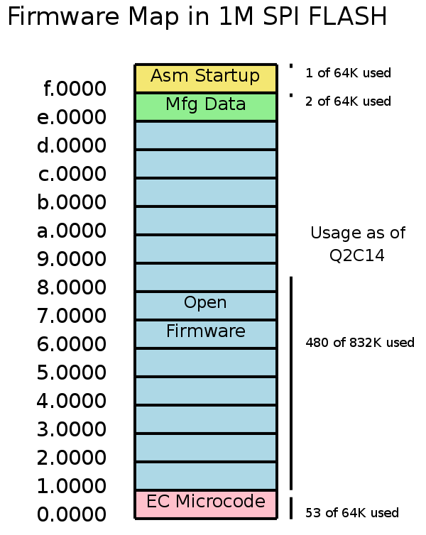
SPI Boot Flash Image
The firmware is stored in an SPI FLASH chip that is directly connected to the EC. The CPU accesses it via the EC, using the LPC bus between the CS5536 companion chip and the EC. The layout of the SPI FLASH is:
- 00000 .. 0ffff 64Kbytes of EC firmware
- 10000 .. dffff The OFW firmware system
- Forth language core
- Open Firmware extensions
- Firmware device drivers
- Filesystem and boot protocol handlers
- Hardware diagnostics
- Icons and audio for the boot screen
- A copy of the Marvell wireless firmware to enable network boot and installation
- e0000 .. ef7ff Reserved
- ef800 .. effff Manufacturing Data: serial number, keyboard type, keys, etc.
- f0000 .. fffff Early startup code
The map above shows the area that is allocated for the different pieces, but at present, there is extra unused room in each piece. See Firmware SPI FLASH Map or its dia source file.
The Marvell wireless firmware is a dropin module. Use .dropins to see the locations and sizes (compressed and uncompressed) of all such modules in OFW. The Marvell firmware is named usb8388.bin.
System Management BIOS Interface
Not Supported
Security
Physical Security
Cable locks can easily be arranged by use of the handles, which have two holes and a carrying handle.
Firmware and Software Security
The firmware and system security and anti-theft system is covered in the Bitfrost specification.
The SPI flash for the XO-1 is being epoxied to the motherboard, to make it very difficult to remove the boot flash intact. The boot flash contents with their keys are the basis for the Bitfrost security model, which has provisions both to protect the systems from viruses and worms, but also an anti-theft system, to protect the systems during transportation and later if desired. #1093 tracks the epoxy implementation.
Indexed register access via the embedded controller to internal registers must also be disabled. #1432 has been entered to track this work.
Firmware Recovery
Space permitting, OLPC hopes to have a (subset) copy of OFW in left-over flash space to be used if somehow the original is corrupted. We do not yet know if there will be sufficient space for a recovery copy; if it exists, it is clear it will have to be a subset of the full OFW.
Power Management Support
As discussed above, Linux does not depend on ACPI. To meet our fast resume goals and transparency into the firmware, we do not use ACPI, which would significantly slow our resume from suspend while adding no benefit. In this regard, we differ significantly from other x86 systems. This is the normal case for Linux on other architectures, so should not be regarded as unusual for Linux overall.
The Trac system can give you a list of all open power related issues (by searching on the keyword "power").
Power Management States
User Visible States
The following are the major operating states of the system. For simplicity's sake in using commonly understood terminology, see Wikipedia's ACPI article.
- Powered Down: This state is called G3 in ACPI terminology Everything is off and the battery can be swapped. The operating system will have to be booted to start operation; the RAM contents are not preserved. If power is available, the EC will be powered up and potentially charging the battery.
- Suspended, with Mesh Active, No screen: A common mode of use will be the system not being used, but still active forwarding in the mesh network on behalf of others in the mesh, but otherwise unused. This differs from our powered down state by the fact the Marvell wireless will be powered up, and active. In ACPI terminology, the closest match is G1/S3. The processor is suspended to RAM (in self-refresh).
- Suspended, with Mesh Active, Screen Enabled: Another common mode of use is sometimes called "ebook mode". Both the screen and the Marvell wireless are left operational: the screen by use of the DCON chip. This differs from our powered down state by the fact the Marvell wireless will be powered up, and active along with the display. In ACPI terminology, the closest match is G1/S3. The processor is suspended to RAM (in self-refresh). Note that the DCON has facilities to implement a "screen saver" where it can disable itself and the backlight after a preset time without requiring the system to be resumed from RAM.
- System fully operational: In this state, the system is available for normal use. The ACPI processor states that this corresponds to are C0 and C1 (note that C1 is not useful on a GX, but does save power on the LX).
Processor Power Management States
The Geode LX processor itself supports the following states (excerpt from the LX processor handbook):
- On (S0/C0): All internal and external clocks with respect to the AMD Geode LX processor are running and all functional blocks (CPU Core, Memory Controller, Display Controller, etc.) are actively generating cycles. This is equivalent to the ACPI specification’s “S0/C0” state.
- Active Idle (S0/C1): The CPU Core has been halted and all other functional blocks (including the Display Controller for refreshing the display) are actively generating cycles. This state is entered when a HLT instruction is executed by the CPU Core. From a user’s perspective, this state is indistinguishable from the On state and is equivalent to the ACPI specification’s “S0/C1” state.
- Sleep (S1): This is the lowest power state the AMD Geode LX processor can be in with voltage still applied to the device’s core and I/O supply pins. This is equivalent to the ACPI specification’s “S1” state. Given that the Geode LX does not drive the video output, and therefore a full DCON synchronization is required to get the display running, it is not clear that S1 will be useful for us (though it would allow computation to start faster than full suspend to RAM).
Power Button
The power button on OLPC serves as a power button.
Momentary Button Push
The system will suspend to RAM after the button is pressed momentarily. Wireless will be left operational when suspended this way. (Prior to deployment of suspend/resume, this button currently performs a clean Linux shutdown). See #1396 for more information.
Four Second Button Push
Pressing the power button for four seconds does a hard reset of the system and all state is lost.
Battery Subsystem
Battery charging is controlled by the embedded controller. Both NiMH and LiFePo battery chemistries are supported by the firmware. The current state of battery charge is reflected in the Home Mode display. It is also available in the developer's activity.
Linux reflects the battery information into the /sys/class/power_supply/olpc-battery directory. The files found in this directory include:
- accum_current
- capacity
- capacity_level
- Full
- Low
- Normal
- current_avg
- health
- good
- overheat
- overvoltage
- manufacturer - Mfg of the supplied battery
- Gold Peak
- BYD
- Unknown
- present - 1 if present and 0 if not
- serial_number - 16 character alpha numeric number
- status - State of the battery's charging
- power supply charging
- power supply discharging
- power supply full
- power supply not charging
- technology - (see bug #1408)
- NiMH
- LiFe
- Unknown
- temp
- temp_ambient
- type - Default Battery
- uevent - Provides listed status of battery attributes
- Name - olpc-battery
- Type - Battery
- Status
- Present
- Health
- Technology
- Voltage_Avg
- Current_Avg
- Capacity
- Capacity_Level
- Temp
- Temp_Ambient
- Accum_Current
- Manfacturer
- Serial Number
- voltage_avg
The battery driver has been modified not to use indexed reads but rather implement using defined EC commands. #1430 will track this work.
Linux reflects the line in information into the /sys/class/power_supply/olpc-ac directory. The files found in this directory include:
- online - Presents 1 if online and 0 if offline
- type - ac
- uevent
- Name - olpc-ac
- Type - Mains
- Online
Switches
There are a number of switches that are intended to help Linux know what the user is doing and take appropriate action; these may be connected to the system either via Geode GPIO's or via the EC. These are not hardwired in the firmware at all, but the following describes the expected behavior under Linux. These generate SCI events, and also generate keyboard scan codes, as documented in the EC specification or in XO-1 GPIO assignments. Power management policy is typically controlled by a user level daemon process (trac #31).
Lid Close Switch
This switch indicates the laptop has been closed. Depending upon the policy set in the power manager, the system may:
- suspend to RAM, powering down everything except the wireless (default behavior), and corresponds to state 1, as described above.
- forcing the screen off, power down the DCON, the video unit, and the video drivers. In principle, the GPU could also be disabled and applications be asked to regenerate their contents on re enable, but we'll probably get most of the power benefit by disabling the GPU when not in use.
Using the 04susp.img suspend/resume NAND image given to Quanta, you can check the presence of the lid switch with the following:
cat /dev/input/event0
You should see (binary) text for both lid down and lid up.
Ebook sense switch
The Ebook sense switch indicates that the hardware is configured as an ebook, though this is just a physical configuration rather than a requirement of what sort of application is running. Depending upon the chosen application, the behavior may differ. #1555 tracks reflecting this to user space.
An ebook reader itself will ask the power manager for aggressive power management. (State 3 as described above; wireless enabled, and screen in DCON driven mode). The screen will be on, being driven at 25 hz, with the DCON configured to turn the screen and back light off after a short timeout.
Using the 404susp.img suspend/resume NAND image given to Quanta, you can check the presence of the ebook mode sensor by looking at the output of dmesg. For example:
[247606.530341] olpc-pm SCI ebook (10, 0)
Thermal Management
The CPU is protected by a fixed over-temperature cut-out at 85 degrees C. By using the ambient temperature reported by the battery system and the known temperature rise over ambient in the system enclosure, we hope to be able to warn users of possible overheating before running into this over temperature cut-out. The CPU can also be "throttled" when over temperature. There may be some ways of reducing internal heat generation, though experimentation of this will wait until a later date. #1410 has been established to track this.
Note that different battery chemistries have limitations on the maximum temperature that they can be charged, and the system can report over temperature to programs via the /sys/class/battery/psu_0/status interface.
Video
Compression Buffer
The Geode has the capability of compressing the video data stream from RAM to the video processor. This could greatly reduce the memory bandwidth used, thereby saving power, and reducing memory contention, increasing system performance. The power versus RAM tradeoffs are not obvious, particularly with the DCON able to take over driving the flat panel, and this will need serious careful investigation with real power numbers and possibly real use data. #1411 has been established to track work on determining if this feature is worthwhile for the XO-1.
Video Drivers
If the GPU is idle for some length of time, (say, several frame times), the data sheet makes clear it might be worth turning off the video drivers to the DCON and switch to DCON mode, to reduce power consumption. As always, we should measure the benefit: the cost here is the latency for the Geode to resume driving the display. We cannot presume the 37ma typical figure is relevant to the XO-1, as we are driving the DCON chip rather than a TFT panel directly.
#1412 has been established to track this issue.
Video Input Port
Is not used, and should be disabled in the driver. See the GLD_MSR_PM Bit Descriptions in the Geode LX processor handbook.
Security Block
The security hardware block in the processor should be turned off whenever not in use. Note that the Geode does this automatically, so long as the right GeodeLink register is set and the hardware is not in use. Therefore this is merely auditing that this register is set correctly by the firmware.
Power Management Kernel Interface
Suspend to RAM
We use the standard kernel interface to suspend to RAM (See http://acpi.sourceforge.net/documentation/sleep.html):
echo mem > /sys/power/state
Test Mode
For OLPC, we needed an way to test the suspend/resume path, without actually suspending. This is useful for making sure that our suspend and resume functions are working well, and it can also help with optimization. To enable this, we added a file to the /sys/power directory:
/sys/power/olpc-pm
To run through through a STR cycle without actually suspending, do this:
echo "test" > /sys/power/olpc-pm
echo "mem" > /sys/power/state
To go back to "real" mode, do this:
echo "normal" > /sys/power/olpc-pm
This may be something valuable for the PM community at large. If not, then we expect this to only be a test file for olpc-pm, and it won't go upstream.
Power Management Scenarios
Power management on the XO will be controlled by a special application known as the Power Management Daemon (or PMD for short). This yet to be defined application will be responsible for processing power events from both Sugar and the kernel and managing the system accordingly. It will use these scenarios as a roadmap for designing the power management policy on the system.
Suspend to RAM
The following are the scenarios we wish to support for Suspend to RAM (STR):
On Demand
The XO enters STR on demand from some application or user input. This does not imply that the user will have a shiny button to press to enter the state, only that the state is not entered automatically by some hardware event or timer. Typically, the PMD would be notified through DBUS to enter the sleep state. The appropriate wakeup events for this mode would be the Power button, RTC and EC - possibly configurable by the requesting application. Enabling LID events will be complex, because presumably we don't want to wake up on the LID down event.
Lid down/up
The XO enters STR when the LID is closed, and resumed when the LID is opened. Upon detecting a lid down event, the PMD enables the LID event as a wakeup event and enters the STR state through the /sys/power/state interface. LID up is configured to wake the system when the lid is lifted again. EC wakeups may be enabled to allow the system to process battery and WLAN events, but the PMD will have to be smart enough to realize that the LID is still down, and it should process the event and go back to sleep again. Since this mode has the LID down, it is not necessary to keep the DCON alive or the backlight enabled. The DCON should be put into a sleep mode before suspending.
System Idle
The XO enters STR when it is believed that the system has nothing to do. The metric used for "nothing to do", as well as the idle time is still largely to be determined. This is the hardest of all modes, and will be done last.
Low battery light
The EC turns on the red led when it thinks the battery is empty. This is by an SOC % dropping < 15%. If the battery voltage depletes further to a level where cell damage will occur it turns the system off.
Operating System Power Management
Linux is working very hard to remove "ticks"; the Linux kernel is now "tickless" and this is operational on OLPC, meaning that it no longer uses a periodic 250 hz timer clock interrupt to drive the scheduling of processes. The X0-1 has been observed at 40 wakeups per second. Work is underway in user space to abolish polling of hardware that might force wakeups, and private communications are that a full Gnome environment has been seen as low as only a few wakeups/second. Note: Independent of the CPU lower state, Linux may have many parts of the system powered down: e.g. audio, video output, etc. as described in detail below.
CPU and Support Chip
The CPU and 5536 automatically gate clocks when the system is idle on most hardware in both chips. Trac #1417 has been created to track verification of the configuration registers that control clock gating.
Given the progressively improving reduction in wakeups in Linux, use of the CPU's S1 is expected to be possible much of the time. We do not yet know how much power this may save. #1416 has been created to track this measurement.
The additional possible savings under program control internal to the LX processor and 5536 are the GPU, video TFT panel drivers, and refresh rate.
The X Window System is in a good position to control the GPU: when the X server is idle, it can shut down the GPU, and drop the refresh rate (see below). #1418 has been entered to track the GPU power management.
Device Power Down
Many external devices in the XO-1 can be powered down when not in use.
Screen Refresh Rate
Up to 100mw of power can be saved by reducing the refresh speed of the screen to 25 hz, which may account for an hour or more of use in ebook mode.
Whenever the X server transitions from not drawing to drawing, the refresh rate should be increased to its normal 50hz at the next vertical retrace. Whenever the X server goes idle, the refresh rate should be dropped to a frame rate of (tbd) at the next vertical retrace. #1419 has been established to track this behavior.
DCON mode
See above section about the video drivers.
Backlight
Given the back light can consume a significant portion of total power, particularly in Ebook mode, its management is important.
In Ebook mode (CPU suspended), there are registers in the DCON chip that allow for the backlight to be turned off automatically without processor intervention.
Recent Gnome versions have dbus messages defined to allow applications (such as DVD players) to temporarily disable the screen saver/DPMS functions of the system (e.g. the Totem video player). The XO-1 power manager and activities should follow these conventions.
The backlight is controlled by the X DPMS extension #1429 has been established to track its implementation..
Audio
The Analog Devices AD1888 can disable all sections it is not using. As it can drive 5.1 audio output, it is important that we verify that all but the stereo channels are disabled.
It also has a "deep sleep" feature, in which it can be entirely disabled. If its device driver is closed, the AD1888 should be put into deep sleep, and restored when the device opened. #1420 has been established to track this verification.
We also need to audit our audio applications that they close the audio device when idle. #1421 has been established to track this verification.
USB
USB and power management are "iffy" at best. Our power manager will probably need to have an option to indicate whether STR (suspend to RAM) should be performed if USB devices are plugged in or not.
We also need to verify that we are properly disabling USB as we suspend and resume. #1423 has been established to track this issue.
Keyboard/Touchpad
At this time, it does not appear that the keyboard and touchpad consume enough power (a few milliwatts) to be a significant battery drain in Ebook mode. This may need to be revisited when we transition to a new lower power wireless module. In BTest-2 and BTest-1, it was inadvertently on the wrong power rail that is not powered during suspend: this is fixed in B3.
SD
The SD slot and CaFE chip section should be powered down whenever the device is closed. #1426 has been established to track verification of this behavior.
Camera
An LED is in series electrically with the camera (B3 and later) to guarantee that users will know if the camera is enabled. The camera and that segment of the CaFE' chip should be disabled when the device driver is closed. #1424 has been established to track this issue.
Camera based activities should be audited that they close the device when idle or when not the current activity; eventual automation of this for standard activities in the tinderbox would be desirable if we can arrange it. #1425 has been established to track this task.
Power Management Policy
Power management is controlled in a number of places, but the policy is primarily controlled by OHM - Open Hardware Manager. The intended policy for OHM power management is still subject to change.
Special Function Keys
One Touch Buttons
Getting started:keyboard and Keyboard shortcuts document the function of buttons in the Sugar user interface. Note that there are no built-in function keys that are built into the BIOS firmware as there may be on a conventional PC: instead, all keys and buttons are left to the user interface software for interpretation. The sole exception to this rule is the power button: by holding the button down for four seconds you can force a hard reset of the XO-1 system.
The two sets of keys which directly affect power consumption are the "volume" control keys for the audio, and the backlight control keys.
Sugar Activities
Sugar activities and their status, along with detailed GUI specifications are available.