Power Management/lang-es
Administración de Energía
- This is an on-going translation
XO-1 Especificación de Software
Introducción y material relacionado
El manejo cuidadoso de la energía de la batería es crítico.
Esta página es un trabajo en curso que recopila información relacionada a la administración de potencia de OLPC.
- Dominios de Energía
- Software de Manejo de Energía
- Trucos y Consejos para la XO
- Mediciones de Energía del LX
- Papers varios sobre Eficiencia Energética en Computación y Redes (en inglés)
Además de efectivamente manejar la energía en la batería, en la página Batería y Energía se discuten varias fuentes alternativas que podrían ser usadas para complementar el actual cargador.
Enfoque de Linux al control de potencia
Linux es una plataforma altamente portable que corre en casi todas las arquitecturas importantes, incluso muchas que son usadas para sistemas embebidos que utilizan baterías. Por ello la infraestructura para manejo de potencia se ha vuelto algo sofisticada en los últimos años, aunque aun esta madurando. Esto significa que las instalaciones son generales y no estan atadas a una arquitectura particular. La primera generación del sistema OLPC, siendo de la parte x86 del mundo es por ello similar y fundamentalmente diferente de otros sistemas basados en x86, por razones que seran claras en la siguiente discusión.
Linux no es dependiente de ACPI o los mas viejos sistemas de administración de potencia APM, que son específicos para x86. Por ello, el diseño de Linux ha siempre hecho su control de potencia en el sistema operativo, y ACPI u otros parecidos son considerados "dependientes de la plataforma".
Innovaciones de la OLPC
El chip DCON nos deja manejar el refresco de nuestro "flat panel" de bajo consumo de potencia y por ello apagar completamente la board del procesador. Dado que nuestro "flat panel" es usable en modo de escala de grises a 1 vatio, usted puede ver que las corrientes de fuga (leakage) y el consumo de potencia de la fuente de poder pueden dominar el consumo de potencia fácilmente. Podemos también ser capaces de dejar que el modulo wireless de Marvell opere independientemente, mandando paquetes por la Mesh mientras que posiblemente todo lo demás este apagado.
Configuración de Hardware
Soporte del CPU
Mas información sobre el CPU puede encontrarse en Wikipedia y AMD.
- Los sistemas BTest-1 y BTest-2 usan el AMD Geode GX-400
- Los sistemas BTest-3 y posteriores usan el AMD Geode LX-700
AMD Geode™ CS5536 Chip Acompañante
Todos los XO-1 usan el AMD 5536. Note que el procesador y el southbridge disponen de extensas facilidades para ahorrar energía ya sea automáticamente o programáticamente. Ejemplos de ello incluye la habilidad de apagar el GPU cuando no esta en uso y apagar la salida de video.
Soporte de Memoria
La XO-1 usa memorias soldadas en la tarjeta madre y no puede ser expandida.
- BTest-1 tienen 256M de RAM y 512M de flash.
- BTest-2-1 tienen 128M de RAM y 512M de flash.
- BTest-2-2 tienen 256M de RAM y 512M de flash.
- BTest-3 y posteriores tendrán 256M de RAM y 1GB de flash.
RAM de Video
La memoria de la pantalla de video de la XO-1 se toma de la memoria principal. Los sistemas basados en el LX usan 16 MB de memoria principal, y los sistemas basados en el GX usan 8 MB.
Recursos del Sistema
Mapa IRQ
| Inter. Sistema |
Conector | Función |
|---|---|---|
| IRQ0 | Temporizador del Sistema | |
| IRQ1 | Teclado PS2 | |
| IRQ2 | Cascada del segundo PIC | |
| IRQ3 | Disponible | |
| IRQ4 | Disponible | |
| IRQ5 | IRQ Audio | AC 97 Audio |
| IRQ6 | Disponible | |
| IRQ7 | PCI INTC# | NAND/tarjeta SD/Cámara |
| IRQ8 | Real time Clock (RTC) Interrupt | |
| IRQ9 | SCI | |
| IRQ10 | USB IRQ | Controladores USB |
| IRQ11 | PCI INTB# | VGA/DCON |
| IRQ12 | Touch Pad PS2 | |
| IRQ13 | PCI INTA# | Procesador matemático |
| IRQ14 | Disponible | |
| IRQ15 | Disponible |
Ruteo de Interrupciones
El siguiente diagrama debe ayudar a entender el ruteo de interrupciones en el X0-1.

Asignación de Recursos DMA
La OLPC no utiliza el DMA ISA. Todos el DMA es efectuado vía el control (mastering) del bus PCI, con lo cual no es necesario una asignación de recursos prefijada.
Soporte de Teclado
Los teclados físicos son idénticos en cualquier XO-1; la información de fabricación en el firmware indica que variante de teclado está instalada. Usamos una versión de interfaz PS/2 de 3.3V para ahorrar energía. No está previsto el conectar dispositivos PS/2 externos.
Energía del Teclado
El teclado y el touchpad se encuentran energizados constantemente tanto en los modos operacional-total como en el suspendido-en-RAM (BTest-3 o posteriores) permitiendo que el teclado reactive (resume) del procesador. En los BTest-1 y BTest-2 el teclado no esta energizado durante la suspensión, debido a un desliz de diseño.
Soporte de Lenguajes en el Teclado
El soporte de lenguaje para el teclado involucra varios ítems:
- Los símbolos en las teclas
- XKB definiciones del teclado para el sistema de ventanas que define el comportamiento del teclado. Estas se encuentran en /usr/share/X11/xkb.
- El mapeo del teclado para la consola (generalmente más sencillo que la definición completa del Sistema de Ventanas X, ya que la consola no esta totalmente internacionalizada.
- Posiblemente métodos de entrada para algunos lenguajes (ej: Chino)
Un diseño de teclado puede ser capaz de soportar múltiples lenguajes y de cambiar de uno a otro.
En este momento los diseños de teclados han sido terminados para las siguientes áreas:
- Arábigo
- Portugués Brasilero
- Francés
- Nigeria (para Inglés, Hausa, Yoruba)
- Castellano/Español
- Tailandés
- Urdu
- Internacional EE.UU. (capaz de ser usado por varios idiomas Europeos occidentales)
Que teclado está instalado, se encuentra codificado en la área de datos de fabricación del firmware, y el soporte de lenguaje correcto para el teclado instalado en la instalación del software.
Definiciones adicionales de teclados son fáciles de generar: métodos de entrada para scripts complejos pueden ser mas difíciles (aunque ya existen varios).
Touchpad
El touch pad/tablet puede ser "recalibrado" bajo comandos de programa a partir de la BTest-3 (probablemente también en las BTest-2-2). Esto re-ajusta la sensibilidad del sensor capacitivo. El Trac bug #1407 esta siendo usado para seguir la implementacion de esta caracteristica relacionada a la energía. Como una medida temporal, recalibrar el touchpad puede ser forzado manualmente.
Hardware Inalámbrico
La XO-1 soporta 88W8388+88W8015, es 802.11b/g compatible; dual ajustable, antenas coaxiales rotables; soporta diversidad de recepcion. Tambien soporta una implementacion de la evolucion del estandart 802.11s mesh network draft.
El consumo de potencia del modulo Marvell wireless ha sido medido como un poco mayor de 300mw; aun con perdidas de fuente de potencia, esperamos que las baterias puedan dar potencia al wireless por > 40 horas (falta ser medido).
Debido a que el problema del "ultimo Kilometro" es tan grave, estamos haciendo ingenieria al sistema con el fin de dejar el wireless activo por la mayor cantidad de tiempor posible, debido a que el wireless pude correr la red mesh autonomamente. El modulo es capaz de despertar la CPU atravez del controlador embebido. El Trac #1060 ha sido establecido para seguir el desarrollo, integracion y verifcacion del modo autonomo mesh.
El firmare del wireless dinamicamente ajusta la potencia transmitida; pero el procesamiento de la senal el receptor determina el consumo de potencia. Marvell ha hecho un extensivo trabajo para minimizar el consumo de potencia automaticamente.
Por ello, esperamos dejar el wireless activo en todos los modos exepto en el modo totalmente apagado (Marcado como estado 1 abajo); este estado tambien nos permite apagar el USB enteramente por que hay una senal del modulo wireless que permite al XO-1 ser despertado por el firmware del wireless.
Adicionalmente, debe haber un modo que cumpla con los rquirimientos de emisiones de la FAA y similares para uso dentro de los aviones, en el cual el wireless pueda ser deshabilitado. Esto no sera facil de accesar por un diseno deliverado. El Bug #1406 esta siendo usado para seguir este tema.
Controlador Embarcado (CE)
El controlador embarcado es un ENE KB3700: File:KB3700-ds-01.pdf. es usado para cargar la bateria, emular varios ¨legacy devices¨ (e.g. PS/2), anadir mas pines GPIO (debido a que el Geode no tiene pines suficientes, algunas senales deben ser ruteadas atravez del CE), bootear el sistema (El flash SPI usado para guardar el firmware es una ROM serial conectada al CE), despertar el sistema bajo varias circunstancias, y otras funciones micelaneas. La especificación del CE contienen informacion detallada acerca de los comandos y protocolos usados para comunicarse con el CE. Un numero de botones (game pad y botones, etc.), estan unidos al CE, y tambien generan codigos de scan como si estos fueran teclas del teclado, para simplificar la interfaz de programacion. Eventos SCI tambien son generados a veces para informar al CPU de eventos, entonces el XO-1 puede evitar interfaces de polling que de otra forma requeririan despertares periodicos del sistema.
Indicadores de Estado
El XO-1 tiene muchos indicadores de estado; algunos de los cuales estan en ambos lados de la unidad principal.
La imagen en la derecha

que es de un sistema BTest-2 tienen la mayoria de ellos, aunque algunos seran usados en diferente forma que los actuales. Los sistemas XO-1 de produccion final les faltara las luces del teclado y tendran luces de indicacion para el microfono y la camara. Una fotografia con marcas de un sistema BTest-3 se anadira tan pronto sea posible (en algun momento en las dos ulimas semanas de mayo).
Luces Inalámbricas
Hay dos luces inalámbricas. Una luz se ve casi como un punto de exclamacion y la otra como (*). Estas son usadas para indicar conectvidad.
- El LED ! es usado para indicar asociacion *y* conectividad via modo infraestructura.
- El LED (*) es usado para indicar una associacion similar y la existencia de un portal mesh.
- Si ninguno esta prendido entonces usted esta tratando de usar una mesh que no esta conectada.
- Si los dos estan encendidos, entonces usted es un portal mesh para una mesh a internet.
Note que este comportamiendo no ha sido aun implementado y requerira trabajo con el demonio NetworkManager, por que alli es el mejor lugar para saber si la conectividad esta disponible. Vea bug #1385 para seguir el progreso.
LED indicador de Prendido
Este LED indica que el sistema esta prendido. Es controlado por el controlador embarcado.
LED de la Batería
El LED de la batería indica información acerca de la batería.
- si el LED está verde, indica que la batería está totalmente cargada.
- si el LED está anaranjado, indica que la batería se está cargando.
- si el LED está rojo, indica que la batería tiene una carga baja críticia.
- si el LED está rojo y titilando, indica un error el sistema de carga de la batería.
Este LED es controlado por la lógica de carga del controlador embarcado.
LED del Micrófono
Si el micrófono esta activado, el LED del micrófono esta prendido. Esta es una característica de Hardware que no pude ser evitada.
LED de la Cámara
Si la cámara esta prendida, el LED de la cámara se prenderá. Esta es una característica de hardware que no puede ser evitada.
Firmware (BIOS en PC's convencionales)
Open Firmware
Aparte de usar una BIOS y boot loader, para la serie "C" de nuestro firmware estamos usando Open Firmware. Ya no usamos LinuxBIOS para el setup de nuestro s¡stema. Este es el resultado de haber implementado un resume fast past resume desde la RAM; una vez esto es implementado, el setup inicial del sistema es casi idéntico.
Tambien hemos removido el soporte VSA y VESA (Soporte de sistemas virtuales del Geode) de nuestro firmware. Ahora que nuestro PCI bus esta arreglado, no tenemos necesidad de registros de configuración del PCI. Similarmente al usar el fbdev driver en Linux, no tenemos necesidad de la emulación VESA; mientras que la emulación del bus PCI era software libre (AMD la hizo disponible generosamente), la emulación VESA fue una parte de VSA que no les pertenecía, y por ello no teníamos fuentes para este. No queríamos un "blob" binario inmantenible en nuestro firmware que no necesitábamos de cualquier forma, y salva espacio en la flash para otros propósitos.
Reinicio (Resume) Rapido
El Resume en nuestro sistema es extremadamente rápido: aun sin ningún intento serio de optimizar el resume, podemos reiniciar desde RAM en 160 milisegundos (mediados-Abril). Creemos que las limitaciones de hardware para el resume son de aproximadamente 63 milisegundos en el B2 y sistemas anteriores; B3 y posteriores son probablemente similares. Trabajaremos mas en el futuro para hacer que el resume sea mas rápido. Note que para la mayoría de usos, 100ms es considerado como el limite de la percepción humana (e.g. tipear).
Identificación del sistema
La pagina Datos de Manufactura documenta la cadena del ID del Modelo, numero de las partes, información de localización, empresa, versión de la BIOS y muchas otros piezas de datos.
Boot "Silencioso"
El booteo no es "silencioso" en este momento. Linux tiene facilidades para hacer un splash screen en el booteo para esconder los mensajes de booteo, pero OLPC no ha implementado esto todavía. El Bug #1394 anota este asunto para su eventual resolución.
POST (Power-On Self Test)
Si la pantalla se prende y el logo de OLPC aparece, una gran parte de la maquina esta funcionando correctamente. Algunos reportes de progreso para pasos previos del comienzo requieren un acceso interno al sistema, usando puertos seriales especiales o adaptadores de hardware de "puerto 80"
La secuencia normal de booteo intenta cargar el SO lo mas rápido posible de los devs mas probables. Típicamente esto toma solo pocos segundos, entonces es difícil leer la información que sale en al pantalla.
Usted puede parar la secuencia de booteo rápido presionando una tecla de juego (cualquiera de los cuatro botones arriba del boton de prendido) justo despues de prender la potencia, presionándolo hasta que la pantalla se prenda. La pantalla dice: "Release the game key to continue", y OFW entonces empieza en modo interactivo. En modo interactivo OFW activa el teclado, prueba los USB dev (los cuales pueden incluir un teclado USB), y le da la oportunidad de interrumpir el conteo de 3 segundos de auto-booteo. Para interrumpirlo, tipee la tecla de escape (La tecla izquierda superior en el teclado principal, cuya leyenda es un X dentro de un circulo). (Si un teclado USB esta conectado, tipee en el en vez de en el teclado principal).
OFW muestra un "ok" prompt para indicar que esta listo para un comando.
La primera linea del texto del banner muestra la versión del hardware, cantidad de memoria y numero serie de la maquina. La segunda linea muestra la cadena de firma del sistema, que incluye la version de firmware. En el ejemplo de abajo, la version de firmware "Q2C11".
Luego muestra el numero de mensajes de progreso, como en este ejemplo:

OLPC B2, 128MB memory installed, S/N SHF70400BD
OpenFirmware CL1   Q2C12  Q2C

Release the game key to continue
Interactive boot
Keyboard probe
USB probe
USB2 devices:
/pci/usb@f,5/wlan@3,0
USB1 devices
Type the Esc to interrupt automatic startup
type 'help' for more information

ok
Para desarrollar diagnosticos de harware mas extensos, typee "test-all".
ok test-all
Open Firmware, Prompt de comandos
Tipee "help" en el prompt ok para tener una lista de comandos OFW comunes. La PUF de OFW resuelven las preguntas mas comunes acerca de como interactuar con el firmware OFW de OLPC.
Booting
OFW representa el progreso de booteo con una secuencia de iconos que muestran los dispositivos que el esta tratando de accesar.
OFW actualmente puede bootear de lso siguientes medios:
- NAND Flash interna (usando el sistema de archivos JFFS2)
- Tarjeta de memoria SD (usando sistemas de archivos EXT3 or FAT)
- USB mass storage (FLASH key o disk drive) (usando sistemas de archivos EXT3 or FAT)
- Ethernet USB (Cableado) (usando protocolos TFTP, NFS, o HTTP)
- Red Wireless (a través del modo infraestructura o mesh) Vea Trac 1431 para booteo wireless boot e instalación.
La secuencia normal de fast-boot - si usted no oprime una tecla de juego después de prender - es:
- Tarjeta de Memoria SD
- NAND flash interna
- Ethernet USB (Cableada)
- Red Wireless
El icono apropiado se muestra una vez que el dispositivo es escaneado.


Si usted presiona una tecla de juego despues de prender (y no tipea "Esc"),la secuencia de boot es:
- Tarjeta de Memoria SD
- USB mass storage (FLASH Key o disk drive)
- NAND flash interna
- Ethernet USB (Cableada)
- Red Wireless
El icono apropiado se muestra una vez que el dispositivo es escaneado.

Cuando OFW carga un archivo de boot de un dispositivo exitosamente, El muestra el icono XO  y ejecuta ese archivo. El icono justo a la izquierda de el XO muestra cual dispositivo fue exitoso.
OFW en OLPC no carga el sistema operativo en un solo paso. En vez de eso, primero carga un archivo llamado "/boot/olpc.fth", que contiene un script ejecutable escrito en el lenguaje de comandos de Open Firmware. El script típicamente sets up argumentos de linea de comando para linux y le dice a OFW que cargue la imagen final del sistema operativo desde otro archivo. Para circunstancias especiales, el script puede hacer otras cosas como realizar actualizaciones del sistema o correr diagnósticos de manufactura. En el caso normal. Usted vera dos ocurrencias del par de los iconos (Icono del dispositivo, Icono del XO). El primer par muestra una carga exitosa del olpc.fth script, el segundo la carga final del sistema operativo.
El retraso de muchos-segundos que ocurre durante el primer intento de carga desde la NAND FLASH es causado por la necesidad de escanear todo el disposito NAND para poder montar el sistema de ficheros JFFS2. Esta es una bien conocida característica del JFFS2 que no es especifica al firmware.
Device Tree
La información de la configuración de hardware es expuesta hacia Linux a través del árbol de dispositivos de OFW. Esta característica también se usa en arquitecturas PPC y SPARC. OLPC esta trabajando con otros en la comunidad usando el árbol de dispositivos para intentar llegar a una Implementación Común. El Bug 1559 es usado para seguir esta unificacion entre los usuarios de la interface del arbol de dispositivos en Linux.
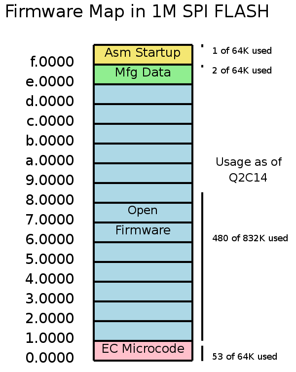
SPI Boot Flash Image
El firmware esta guardado en chip SPI FLASH que esta directamente conectado al CE. El CPU lo accede a través del EC, usando el bus LPC entre el chip acompañante CS5536 y el CE. La disposición del SPI FLASH es:
- 00000 .. 0ffff 64Kbytes de firmware del CE.
- 10000 .. dffff El sistema de firmware OFW
- Núcleo de lenguaje Forth
- Extensiones de Open Firmware
- Firmware de los drivers de los dispositivos
- Sistema de Archivos y manejadores del protocolo de boot
- Diagnósticos de Hardware
- Iconos y audio para la pantalla de boot
- Una copia del firmware wireless de Marvell para permitir el boot e instalación por red
- e0000 .. ef7ff Reserved
- ef800 .. effff Datos de Manufactura: numero serial, tipo de teclado, teclas, etc.
- f0000 .. fffff Código de comienzo temprano
El mapa de arriba muestra el area que esta localizada para las diferentes piezas, pero actualmente, hay unespacio extra sin usar en cada pieza. Vea Mapa Firmware SPI FLASH o su código fuente dia.
El firmware wireless de Marvell es un modulo dropin. Use .dropins para ver la ubicación y tamaño (comprimido y sin comprimir) de todos esos modulos en OFW. El firmware Marvell es llamado usb8388.bin.
System Management BIOS Interface
No Soportado
Seguridad
Seguridad física
Las cerraduras de los cables pueden ser fácilmente arreglados usando clavijas, las cuales tienen dos huecos y una clavija de carga.
Seguridad de Firmware y Software
La seguridad del sistema y del firmware y el sistema anti-robo están cubiertas en Bitfrost specification (o localmente en castellano).
El SPI flsh para el XO-1 esta siendo pegado (epoxied) a la tarjeta madre, para hacer muy difícil de remover el flash boot intacto. Los contenidos de la flash boot con sus llaves son la base del sistema de seguridad Bitfrost, que tiene previsiones para protejer el sistema de virus y gusanos, pero también un sistema anti-robo, para protejer el sistema durante la transportación y después si es necesario.
El acceso al registro indexado a través del controlador embebido hacia los registros internos debe tambien ser desabilitado. Trac 1432 ha sido hecho para seguir este trabajo.
Recuperación del Firmware
Dependiendo en el espacio, OLPC espera tener un (subset) copia de OFW en un espacio sobrante de flash para ser usado si de alguna forma el original es corrupto. Aun no sabemos si habrá suficiente espacio para una copia de recuperacion; si este existe, Es claro que esta tiene que ser un subset del OFW completo.
Suporte para Manejo de Potencia
Como se discutió arriba, Linux no depende de ACPI. Para alcanzar nuestros objetivos de un resume rápido y la transparencia en el firmware, nosotros no usamos ACPI, lo cual haría significativamente mas lento nuestro resume desde suspensión y no añadiría ningún beneficio. En este aspecto diferimos significativamente de otros sistemas x86. Este es el caso normal para linux en otras arquitecturas, entonces esto no debe ser visto como inusual para linux en conjunto.
El sistema Trac puede darle una lista de los temas abiertos acerca dela energia (buscando por lapalñabra clave "power").
Estados de Administración de Potencia
Estados Visibles para el Usuario
Los siguientes son los principales sistemas de operación del sistema. Para simplicidad acerca de la terminología comúnmente usada vea Wikipedia's ACPI article.
- Apagado (Completo): En este estado, (G3 en este estado en ACPI). Todo esta apagado y la batería puede ser cambiada. El sistema operativo tendrá que ser booteado para empezar operación; la RAM no es preservada. En nuestro hardware, si hay potencia disponible, el CE sera prendido y se podra cargar la batería potencialmente.
- Suspendido, con la Mesh Activa, No pantalla: Un modo comun de uso sera el sistema no siendo usado,pero un but still active forwarding in the mesh network on behalf of others in the mesh, but otherwise unused. This differs from our powered down state by the fact the Marvell wireless will be powered up, and active. In ACPI terminology, the closest match is G1/S3. The processor is suspended to RAM (in self-refresh).
- Sistema completamente operacional: En este estado, el sistema está disponible para su uso normal. En estados de procesador ACPI correspondería C0 y C1 (nota que C1 no es de utilidad en un GX, pero si ahorra energía en el LX).
Estados de Energia del Procesador
El procesador Geode LX soporta los siguientes estados (Aparte del handbook del procesador LX):
- En (S0/C0): Todos los relojes externos e internos con respecto al procesador AMD Geode LX estan corriendo y todos los bloques funcionales (núcleo CPU, controlador de memoria, Controlador de Display, etc.) son ciclos activos de generación. Esto es equivalente a las especificaciones de ACPI en el estado “S0/C0”.
- Idle Activo (S0/C1): El nucleo del CPU ha sido detenido y todos los otros bloques fundamentales (incluyendo el controlador del display para refrescar el display) están generando ciclos activamente. Se accede a este estado cuando una instrucción HLT es ejecutada por el núcleo del CPU. Desde la perspectiva de un usuario, este estado es indistinguible del estado On y es equivalente al estado “S0/C1”de las especificaciones del ACPI.
- Sleep (S1): Este es el estado de menor potencia en el cual el AMD Geode LX processor puede estar con un voltaje aun aplicado al núcleo del dispositivo y a los pines de fuente de I/O. Dado que el Geode LX no maneja la salida del vídeo, una completa sincronización del DCON es requerida para hacer que el display funcione , no es claro que S1 sea útil para nosotros (Aunque permitirá que la computación empiece mas rápido que cuando se suspende totalmente a la RAM).
Botón de Prendido/Apagado
Este botón en OLPC sirve como botón de prendido/apagado.
Presión de Botón Momentanea
El sistema se suspenderá a RAM después de que el botón sea oprimido momentareamente. la wireless seguira operacional mientras que se suspenda de esta forma. (Antes de el lanzamiento del suspend/resume, este botón actualmente hace un apagado limpio de Linux). Vea bug #1396 para mas información.
Presión del Botón por Cuatro Segundos
Presionar el botón de prendido/apagado por cuatro segundos resultara en un reset duro del sistema y todos los estados se perderan.
Subsistema de la Batería
La carga de la batería es controlada por el controlador embebido, las dos químicas de las baterías (NIMH LiFePo) están soportadas por el firmware. El actual estado de la carga esta reflejado en el display Home Mode. También esta disponible en la actividad de desarrollo.
Linux refleja la informacion de la batería en el directorio /sys/class/battery/psu-0. Los archivos en este directorio incluyen:
- capacity_percentage - porcentaje de batería faltarte
- current - la corriente siendo substraída/añadida a la batería
- device - link hacia ../../../../devices/platform/olpc-battery.0
- name - OLPC battery
- power
- modaliasas - olpc-battery
- power
- psu_0
- psu_1
- subsystem - link hacia ../../../bus/platform
- uevent
- status - e.g. present discharging o present charging discharging
- status-cap - capabilities e.g. present low full charging discharging overtemp critical
- subsystem - link hacia ../../../../class/battery
- technology - unknown?? (see bug #1408)
- temp1 - en millivolts
- temp1-name - battery
- temp2 - en millivolts
- temp2_name - ambient
- type - battery
- uevent
- voltage - voltage de entrada
Linux refleja la información de la linea de entrada en el directorio /sys/class/battery/psu-1. Los archivos encontrados en este directorio incluyen:
- name - OLPC AC
- power
- wakeup
- status - on-line o off-line
- status_cap capacidades on-line ?? (vea bug #1409)
- subsystem link hacia ../../../../class/battery
- type - ac
- uevent
Note que Linux esta en el proceso de revisar su interfaz de baterías y que esta interfaz cambiara para aceptar esa revisión. Tambien necesitamos convertir el driver de la batería desde las lecturas indexadas hacia los recientemente definidos comandos CE. Trac #1430 Seguirá este trabajo.
Switches
Hay un numero de switches que estan hechos para ayudar a Linux saber que esta haciendo el usuario y tomar una accion apropiada; Estos pueden estar conectados en el sistema atraves de los GPIO del Geode o a traves del CE. No estan cabaleados en el hardware hacia el firmware, pero lo siguiente describe el comportamiento esperado bajo Linux. Los switches generan eventos SCI y tambien generan codigos de escaneo del teclado,como se documenta en Especificación del EC o en asignaciones GPIO del XO-1. La politica de manejo de Potencia es tipicamente controlada por un user level daemon process (trac #31).
Lid Close Switch
Este switch indica que la laptop ha sido cerrada, Dependiendo de la política de la administración de potencia, el sistema puede:
- suspenderse hacia RAM, apagando todo excepto el wireless (comportamiento por omisión), y corresponde al estado 1, como se describe arriba.
- Forzar apagado de la pantalla, apagar el DCON, la unidad de vídeo, y los drivers de vídeo. En principio, el GPU puede también ser deshabilitado y las aplicaciones se les pide regenerar sus contenidos al re-habilitar, pero probablemente obtendremos el mayor beneficio de potencia deshabilitando el GPU cuando no este en uso.
Usando la imagen NAND 04susp.img suspend/resume dada a Quanta, Usted puede chequear la precesncia del lid switch con lo siguiente:
cat /dev/input/event0
Usted debera verYou texto (binario) para el lid down y el lid up.
This switch indicates the laptop has been closed. Depending upon the policy set in the power manager, the system may:
- suspend to RAM, powering down everything except the wireless (default behavior), and corresponds to state 1, as described above.
- forcing the screen off, power down the DCON, the video unit, and the video drivers. In principle, the GPU could also be disabled and applications be asked to regenerate their contents on re enable, but we'll probably get most of the power benefit by disabling the GPU when not in use.
Using the 404susp.img suspend/resume NAND image given to Quanta, you can check the presence of the lid switch with the following:
cat /dev/input/event0
You should see (binary) text for both lid down and lid up.
Sensor del switch Ebook
El sensor del switch Ebook indica que el hardware esta configurado como ebook. aunque esto es solo una consideración física mas que un requerimiento de que tipo de aplicación se esta corriendo. Dependiendo en la aplicación escogida, el comportamiento puede diferir.
El mismo lector ebook pedirá al administrador de potencia una agresivo manejo de potencia. (Estado 3 como se describe arriba; wireless activada y pantalla en el modo conducido por el DCON). la pantalla estará prendida, siendo conducida a 25 hz, con el DCON configurado para apagar la pantalla y la luz de atrás después de un corto Timeout.
Usando la imagen NAND 404susp.img suspend/resume dada a Quanta,Usted puede probar la precencia de el sensor de modo ebook mirando la salida de dmesg. Por ejemplo:
[247606.530341] olpc-pm SCI ebook (10, 0)
Manejo de Temperatura
El CPU esta protegido por un corte de temperatura fijo a 85 grados C. Usando la temperatura ambiente reportada por el sistema de la batería y el aumento conocido de la temperatura obre la ambiental en el recinto del sistema, esperamos poder avisar a los usuarios de un posible sobrecalentamiento antes de llegar a este limite de temperatura. la CPU también puede ser "sofocada" cuando hay un sobre-calentamiento.
Puede haber algunas formas de reducir la generación interna de calor, aunque esta experimentación esperara hasta una fecha posterior. Bug #1410 ha sido establecido para seguir esto.
Note que las diferentes químicas e las baterías tienen limitaciones en la temperatura máxima a la cual pueden ser cargadas, y el sistema puede reportar sobre-temperatura a los programas a través de la interfaz /sys/class/battery/psu_0/status.
Video
Buffer de Compresion
El Geode tiene la capacidad de comprimir el stream de datos del video desde la RAM hacia el procesador de vídeo. Esto puede reducir en gran medida el ancho de banda de memoria usada, por ello ahorrando potencia, y reduciendo la contención de memoria, incrementando la capacidad del sistema. Las compensaciones de la RAM vs la potencia no son obvias, particularmente ya que el DCON es capaz de manejar el panel plano y esto necesitara una cuidadosa investigación con numeros reales de potencia y posiblemente datos de uso real. Bug #1411 ha sido establecido para determinar si esta caracteristica es util para el XO-1.
Video Drivers
Si el GPU esta en marcha lenta por algo de tiempo (digamos, muchos tiempos de cuadro), el data sheet dice claramente que podría ser útil apagar los divers de vídeo hacia el DCON y cambiar a modo DCON, para reducir el consumo de potencia. Como siempre, debemos medir el beneficio: el costo acá es la latencia para que el Geode resuma y maneje el display. No podemos presumir que la figura típica de 37ma es relevante para el XO-1, ya que estamos manejando el chip DCON en vez de un panel TFT directamente.
Trac bug #1412 ha sido establecido para seguir este asunto.
Video Input Port
No es usado y debería ser deshabilitado en el driver. Vea las descripciones del Bit GLD_MSR_PM en el manual del procesador Geode LX.
Bloque de Seguridad
El bloque de seguridad del hardware debe ser apagado cuando no este en uso.
Administración de Energía del Sistema Operativo
Linux esta trabajando muy duro para remover los "ticks"; el kernel de Linux es ahora "tickless" y esto es operacional en OLPC, esto significa que ya no se utiliza la interrupcion de conteo a 250hz para manejar la programcion de los procesos. En el X0-1 se han observado 40 "wakeups" por segundo. Hay trabajo en camino en el espacio del usuario para abolir polling de hardware puedan forzar "wakeups" y comunicaciones privadas dicen que un ambiente completo Gnome se han visto solo unos wakeups por segundo.Nota: Independiente del estado mas bajo del CPU, Linux puede tener muchas partes del sistema apagadas por ejemplo: audio, salida de video , etc. como se describe en detalle abajo.
Linux is working very hard to remove "ticks"; the Linux kernel is now "tickless" and this is operational on OLPC, meaning that it no longer uses a periodic 250 hz timer clock interrupt to drive the scheduling of processes. The X0-1 has been observed at 40 wakeups per second. Work is underway in user space to abolish polling of hardware that might force wakeups, and private communications are that a full Gnome environment has been seen as low as only a few wakeups/second. Note: Independent of the CPU lower state, Linux may have many parts of the system powered down: e.g. audio, video output, etc. as described in detail below.
CPU y Chip de Soporte
En el CPU y el 5536 las compuertas se "temporizan" cuando el sistema esta "dormido" en la mayoría del hardware en los dos chips. Trac #1417 ha sido creado para seguir la verificación de los registros de configuración que controlan la temporización de las compuertas.
Dada la mejorada y progresiva reducción de los "wakeups" en Linux, el uso de los S1 de los CPU, se espera que sea posible la mayoría del tiempo. No sabemos aun cuanta energía se pueda ahorrar. Trac #1416 se ha creado para seguir esta medición.
los ahorros adicionales de energía bajo el control interno de programa en el procesador LX y el 5536 son el GPU, los drivers del panel de vídeo TFT, y la tasa de refresco.
El sistema X Window esta en buena posición para controlar el GPU: cuando el servidor x esta "dormido", este puede apagar el GPU, y hacer caer la tasa de refresco (vea abajo). Trac #1418 ha sido hecho para seguir el manejo de potencia del GPU.
The CPU and 5536 automatically gate clocks when the system is idle on most hardware in both chips. Trac #1417 has been created to track verification of the configuration registers that control clock gating.
Given the progressively improving reduction in wakeups in Linux, use of the CPU's S1 is expected to be possible much of the time. We do not yet know how much power this may save. Trac #1416 has been created to track this measurement.
The additional possible savings under program control internal to the LX processor and 5536 are the GPU, video TFT panel drivers, and refresh rate.
The X Window System is in a good position to control the GPU: when the X server is idle, it can shut down the GPU, and drop the refresh rate (see below). Trac #1418 has been entered to track the GPU power management.
Apagar Dispositivos
Muchos dipositivos externos en el XO-1 pueden ser apagados cuando no estén en uso
Tasa de Refresco de la Pantalla
Hasta 100mw de energía pueden ser ahorrados controlando la velocidad de refresco de la pantalla. Esto es muy significativo en modo Ebook
Cuando las transiciones del servidor X desde pintura hacia no pintura. La tasa de refresco debe ser incrementada ha sus normales 50hz en la siguiente retrasa (retrace) vertical. En cualquier momento que el servidor x este en marcha lenta, la tasa de refresco debe ser bajada a una taza de cuadro (tdb) en el próximo retraso (retrace) vertical. Trac #1419 ha sido hecho para seguir este comportamiento.
DCON mode
Vea la sección de arriba acerca de pilotos de vídeo
Backlight
Dado que el Backlight puede consumir una porcion significativa de la energia total, particularmente en modo Ebook, su manejo es importante.
En modo Ebook (CPU suspendido), hay registros en el chip DCON que permiten que la bateria se apague automaticamente sin intervension del procesador.
Versiones recientes de Gnome tienen mensajes dbus definidos para permitir aplicaciones (como los DVD players) para deshabilitar temporalmente las funciones de pantalla ahorro/DPMS del sistema (como el Totem Video Player). El administrados de enerigia de XO-1 y las actividades deberian seguir estas convensiones.
El backlight es controlado por la extensión X DPMS. Trac #1429 ha sido hecho para seguir esta implementación.
Audio
Los dispositivos análogos AD1888 pueden deshabilitar todas las secciones que no se estén usando. Como puede manejar una salida de audio de 5.1, es importante que verifiquemos que todos los canales menos los estereo estén deshabilitados.
El AD1888 tambien tienen una caracteristica "deep sleep", en la cual puede ser enteramente deshabilitado. Si su driver de dispositivo esta cerrado, el AD1888 debe ser puesto en "deep sleep" y restaurado cuando el dispositivo se reabra. Trac #1420 ha sido hecho para seguir esta verificación.
USB
El USB y la administracion de Potencia son "iffy" (Maximo). Nuestro administrador de energia probablemente necesitara tener una opcion para indicar si STR (suspender hacia RAM) debe ser realizado si hay dispositivos USB conectados o no.
También necesitamos verificar que estamos deshabilitando apropiadamente el USB mientras suspendemos y resumimos. Trac #1423 se ha hecho para seguir este tema.
Teclado/Touchpad
En este momento, no parece ser que el teclado y el touchpad coonsuman suficiente energia (unos pocos milivatios) para que hagan un gasto significativo de la batería en modo Ebook. Esto puede ser revisado cuando hagamos una transición a un nuevo modulo wireless de menos energía. En BTest-2 y BTest-1, estaba inadvertidamente en un erróneo carril de energía que no tiene potencia durante la suspensión: esto esta arreglado en B3.
SD
El slot SD y la sección del chip CaFE deberían ser apagadas cuando el dispositivo este cerrado. Trac #1426 ha sido establecido para seguir la verificación de este comportamiento.
Camara
Un LED esta en serie (eléctricamente) con la cámara (B3 y posteriores) para garantizar que los usuarios sepan si la cámara esta activada. La cámara y el segmento del chip CaFE deben ser desactivados cuando el driver del dispositivo este cerrado. Trac 1424 ha sido establecido para seguir este tema. Las actividades relacionadas a la cámara deben poder cerrar el dispositivo cuando estén en marcha lenta (idle) o cuando no este abierta la actividad; una automatización eventual de esto para las actividades estándar en el thinderbox seria deseable si podemos arreglarlo. Trac #1425 ha sido establecido para seguir este tema.
Teclas de Función Especial
Botones de un solo Toque
Las Instrucciones de Sugar documentan la función de los botones en la interfaz de usuario Sugar. Note que no hay teclas de función que estén comunicadas con el firmware de la BIOS como se pudiera ver en un PC convencional: al contrario, todas las teclas y botones se dejan para que el software de la interfaz de usuario los interprete. La única excepción a esta regla es el botón de prendido: presionando el botón hacia abajo por cuatro segundos usted puede forzar un reset "duro" del sistema del XO-1. Las dos clases de teclas que afectan el consumo de energía son las teclas de control de "volumen" para el audio y las teclas de control de la luz de la pantalla.
Actividades de Sugar
Las Actividades de Sugar y su estado, así como también especificaciones detalladas del GUI están disponibles.