User:Az990tony/edublog-beta-hw
This hardware was built for the Educational_Blogger_Project .
In this section, I show
- The parts that I purchased to put the hardware together
- The method of assembling the parts into one machine
- Final steps to set up the BIOS
See also the Software stack page.
Parts List
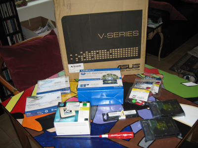
The following system was built from parts purchased at [SWS Electronics and Computers ] a local computer parts store in Tucson, Arizona (USA).
- [[ http://www.asus.com/products.aspx?l1=1&l2=1&l3=380&l4=0&model=1679&modelmenu=2 | V3-M2A690G barebones PC ]]
- tower case
- power supply
- includes one black SATA power connection cable
- [[ http://www.asus.com/products.aspx?modelmenu=1&model=1585&l1=3&l2=101&l3=496 | M2A-VM motherboard ]]
- ATI SB600 RAID controller
- ATI Radeon 1200 Graphics
- 8 USB ports (four in front panel, four in back)
- Multi-card reader SD/MMC/MiniSD/Compact Flash
- One built-in NIC (1GbE gigabit ethernet)
- includes one 18-inch red SATA connection cable
- includes small bag of extra screws, however I ran out and had to go get more
- AMD Athlon64 X2 dual-core 2.3 Ghz processor with heatsink/fan
- The AMD single-core Sempron might have also met the CPU requirement
- Two extra NIC cards (PCI)
- One DVD-RW drive, attached on primary IDE-Master, [[ http://us.liteonit.com/us/index.php?option=com_content&task=view&id=221&Itemid=67 | Lite-On DH-20A4H ]]
- Two SATA drives, 160GB each.
- One 2GB DIMM
- One extra power-plug cable (converts white EIDE to black SATA power connector)
- One extra 18-inch red SATA cable
Assembling the Parts Together
I had purchased two extra red SATA cables, but then learned that one was already included with the Barebones PC. Also, had to go back to the store for an extra EIDE-to-SATA (white to black) power cable adapter. The phillips screwdriver #2 (shown with red handle) is all that you need for tools.
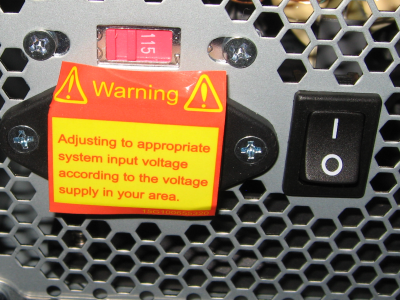
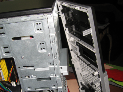 Remove left side and front panels.
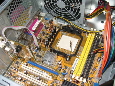
Since this motherboard has an AM2 socket, we could have gone with either an AMD Sempron or Athlon64 X2. I chose the Athlon64 X2 which was more expensive, but runs faster.
Installation was tricky, and I watched some YouTube videos to see how others had done this. Remember to always hold the processor by the edges, and never let the gold pins touch your skin or anything else because you will leave small amounts of oil or sweat that might ruin it.
To install, raise the shiny lever (shown in the up position above), align the corner with the triangle on the chip with the triangle on the motherboard (it is the corner nearest the power supply in the picture above). Line up all the pins, and push down into place. If it didn't work, lift the CPU up, and try again. Once in place, move the shiny lever back down to snap everything in place. If you fail to do this step correctly, you might end up buying another CPU.
The CPU comes with a sticker indicating the type of processor. I affixed this to the front panel.
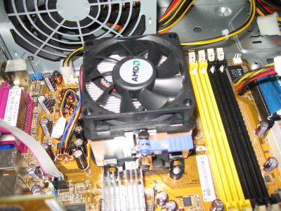
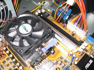
The fan was also a bit tricky. There are two silver brackets. Align the fan so that the blue-purple level is away from the power supply. Put the fan on the processor, and snap in the bracket that is nearest the power supply. Turn the lever all the way to the left, push down on the fan, and attach the other bracket. This second bracket is then made tighter by turning the blue-purple lever clockwise until it is snug against the processor.
Connect the fan to the power cable connection on the edge of the motherboard. The plug is slotted, so you can only put it in one direction.
There are four slots for memory, two yellow and two black. Starting near the CPU, they are:
- DIMM_A1 (yellow)
- DIMM B1 (yellow)
- DIMM A2 (black)
- DIMM B2 (black)
Channel A is A1,A2 and Channel B is B1,B2. If you are going to have DIMMS in both channels, then A1+A2 amount must match B1+B2. All of them need to be the same speed, either 533, 667 or 800. I could have gotten two 1GB DIMMs in A1 and B1 to get dual-channel, but it was cheaper to get one 2GB DIMM, use only a single channel and put it in A1. (Read the [[ http://support.asus.com/download/download.aspx?SLanguage=en-us&model=V3-M2A690G | ASUS Manual ]] if you need more details on this.
To install, push the white tabs down on both sides of the yellow slot. Insert the DIMM, there is a notch with 112 connections on one side, and 128 connections on the other side, so there is no way to put it in backwards. As before, don't let the connections touch your skin or anything else.
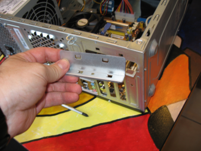
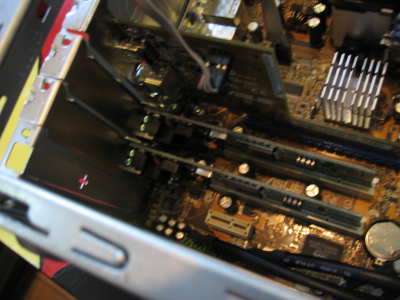
Before you can install the two PCI-based NIC cards, you have to remove the back plates and this holding bracket. Using your screwdriver, twist off the two metal plates for the two PCI slots. You have to slide this bracket out (shown here in my hand) and it was not obvious which way to push, pull or squeeze to get it. It is "left and up" as shown in this picture.
Don't let the connections touch your skin or anything else. Firmly push each one into place, then put the bracket back using "down and right" to hold the cards in place.
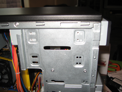
You will need to remove the right side panel as well for this. On the back of the DVD there is a small plastic jumper that slides over two pins. Make sure it is in the "Master" position, and if not pull it off, and put it back on the right way. Most CD and DVD drives assume they will be "Slave" so are often configured for that already. Slide the DVD drive through the top slot of the front panel. Make sure the front face is lined up with the card reader. Wiggle until the holes are visible and apply the screws from both left and right sides to minimize vibration.
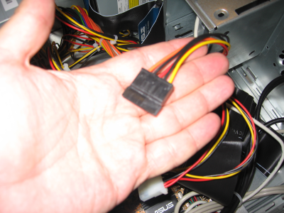
This was a good time to count my power cables. There were plenty of EIDE (white) plugs available, but only one black SATA power plug (shown in my hand here). I had to go back to the store to get an extra EIDE-to-SATA-power adapter.
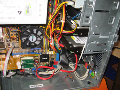
The two SATA drives are "internal" so are pushed in from the inside into place. This was quite difficult because (a) the CPU heatsink/fan was in the way, (b) the Multi-card reader was already in place, and (c) the power cables were in the way. It might have been better to do the steps in the following order:
- Identify the cables needed and tuck the rest behind the metal frame out of the way
- Put in the DVD and all of the SATA drives first, before the CPU and heatsink/fan
- Connect the cables last
For EIDE, there were two flat-ribbon cables. One for the floppy, and one for the Primary Master/Slave. Since we have two drives and plan to attach them to SATA instead, we can put the DVD on as Primary/Master. (I am glad I moved the jumper ahead of time, it would have been difficult to reach once in place!)
For SATA, the Barebones PC already came with one red signal cable, so I had to purchase a second one. There are two kinds of cables. One type of cable has straight connection on one end, and 90-degree bend at the other. The other type of cable has straight connections on both sides. If you have a 90-degree bend at one end, that end goes into the drive. The straight end connects to the motherboard.
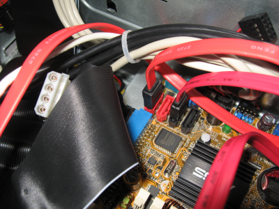 Connecting the SATA signal cables.
I should have read the manual on this one. Instead, I could not see which of the four connectors were SATA1 and SATA2, so I tried several combinations until I finally gave up and downloaded the manual. As shown here, they are (from left to right)
- SATA 1 (red)
- SATA 3 (red)
- SATA 2 (black)
- SATA 4 (black)
If we were using the hardware BIOS-assisted RAID (known also as "fakeraid") this might have been important, but we aren't, and Linux managed to figure out where everything is. Having one on red and one on black probably spreads the I/O across both channels evenly.
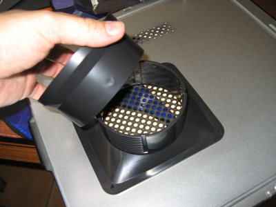
The left side panel has some extra "air vent" plastic, and with it in its fully extended position would not fit back. Turn the plastic 90 degrees and push down to have a low profile so that it will clear the CPU heatsink fan.
Configuring the BIOS
Plug in keyboard, mouse, monitor, ethernet cable, and electricity. The power button is located on the lower right corner of the front panel. It will light blue when the system is running.
Some changes to the BIOS were necessary.
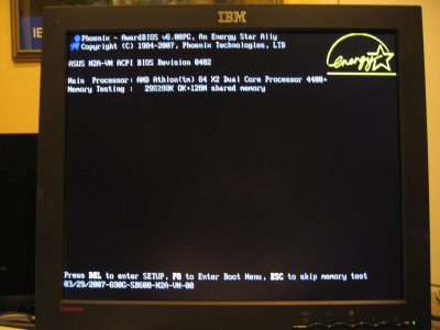
When you boot up the system, it will tell you what BIOS level it is running. I checked with the ASUS Web site and found 0402 is fairly recent (March 2007). There was one newer one 0602 (November 2007) but decided to leave it alone.
Press "Delete" (DEL) button to launch the BIOS configurator.
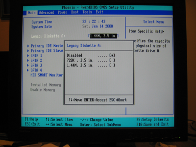 BIOS Configurator - Main Screen.
Here is the main screen of the BIOS configurator. I disabled the Floppy drive, since we don't have one, and that eliminates all of the Linux images from looking for it, and configuring /dev/fd0 device type.
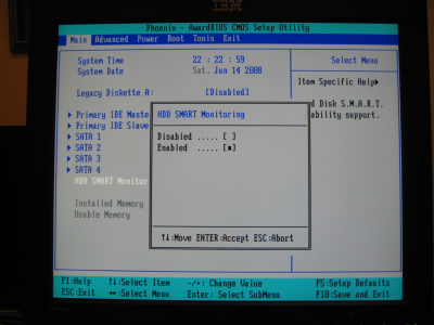
I was told the Western Digital drives I was using were SMART-capable, so I enable this in the BIOS. This will provide some early warning if a drive is experiencing temporary errors.
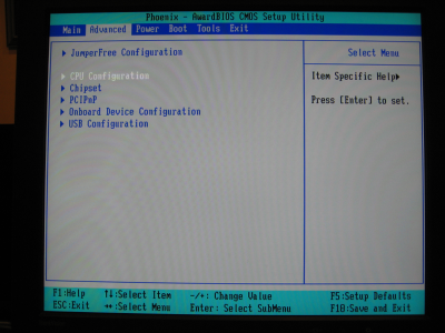
Hit the "right arrow" button to move to the next screen for "Advanced" settings.
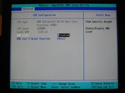
On this screen, I am able to confirm the speed and type of processor, Dual Core AMD Athlon64 at 2300Mhz (2.3 GHz) per core. The settings for "AMD Live!" and Cool'N'Quiet function I left to their default settings.
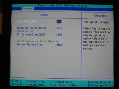
By default this was set to "No". It should be "Yes" for 2.6-based Linux kernels.
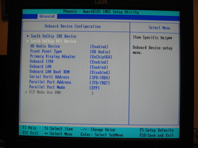
I set the "Primary Display Adapter" to "On Chip VGA". This system has HDMI and other video outputs that we are not using since it is "headless server".
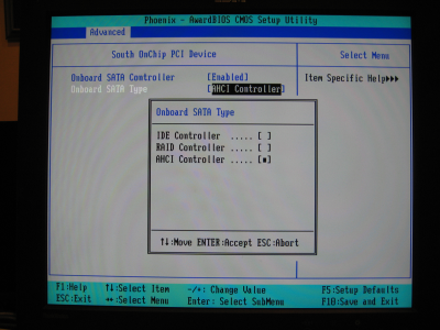
I spent a few days on this setting. Here is what I found.
- IDE - for older Linux kernels, this provides compatability with EIDE drives
- RAID - for newer Windows systems, this provides BIOS-assisted RAID 0, 1 or 10.
- Unfortunately, "fakeraid" does not support the ATI SB600 yet.
- AHCI - for newer Linux kernels, this is the preferred choice.
(We will investigate software-based raid "dmraid" instead)
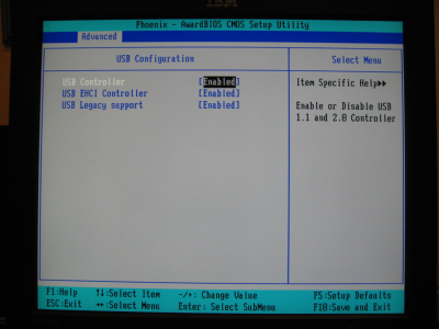
These were all on by default, so I left them as is. While this beta server may not use USB much in Pennsylvania, in general XS School Servers do use the USB, so you want to make sure these are enabled properly.
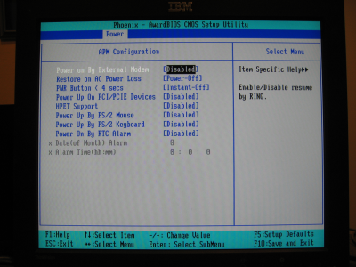
I left all the defaults as is.
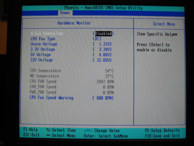
This was perhaps the most important setting. When I first started up the system, the fan was going painfully slow, around 900 to 1100 RPM, and the chip was over-heating. (Greg, I can confirm we can run this CPU to 67 degrees C!) I took it back to the store to see if there was something wrong with the heatsink fan (or maybe I broke it during the install), but they told me that it was a simple BIOS change, you must DISABLE the Q-Fan Controller.
This screen is good to watch to make sure the fan run around 2700 to 3000 RPM.
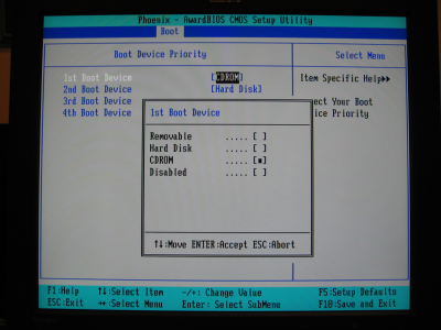
Since we will be installing software from XS LiveCD, it is important to make the CDrom first in the boot order. If this BIOS supported USB as a choice, I would have made it second on the list.
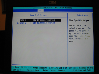
This shows the device types of the Western Digital 160GB SATA 7200 RPM drives.
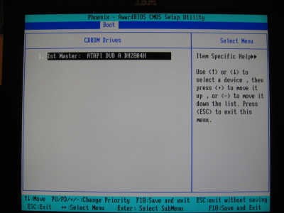
This shows the type of CD/DVD burner.
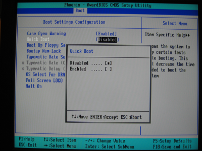
My friend Ken suggested this one. If you disable Quick Boot, then it goes and spends 20-30 seconds testing the memory. Normally you only have 2-3 seconds to hit the "DEL" button to go to the BIOS configurator. With 20-30 seconds, you have time to remove any CDs or insert any CDs needed for booting, or to go into the BIOS configurator tool.
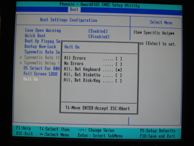
The "All, But Keyboard" means that if the keyboard is not attached, then that is acceptable and to continue. This is typical of a "headless server".
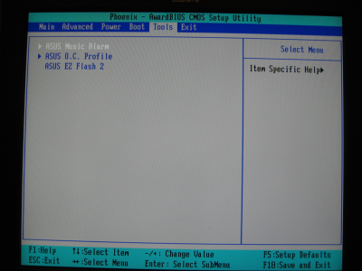
If we ever need to update the BIOS, the EZ Flash tool is here. I downloaded the 0602 level of the BIOS onto a USB memory key, chose this tool, and it found the USB Memory key as "B:" drive to perform the update.
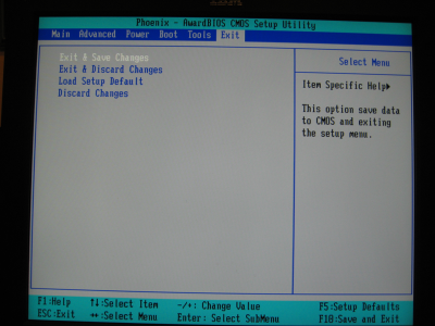
Press function key F10, or choose the option here to "Save and Exit". There is an option to return to default settings, and to discard changes.
